Heat exchanger energy recovery device

An energy recovery device and heat exchanger technology, applied in the field of energy recovery device and heat exchanger energy recovery device, can solve problems such as low energy recovery rate, and achieve the effect of intelligent ventilation heat recovery system

Inactive Publication Date: 2020-09-04
刘长庚 +2
View PDF19 Cites 0 Cited by
  • Summary
  • Abstract
  • Description
  • Claims
  • Application Information

AI Technical Summary

Problems solved by technology

[0004] In view of the above facts, the purpose of the present invention is to solve the problem of low energy recovery rate in existing energy recovery devices, and then design a heat exchanger energy recovery device with high energy recovery rate

Method used


Image

  • Heat exchanger energy recovery device
  • Heat exchanger energy recovery device

Examples


Embodiment 1

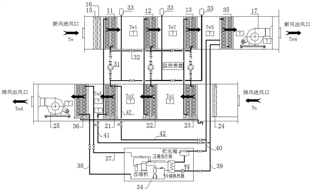
[0057] Example 1: see figure 1 , A heat exchanger energy recovery device of this embodiment includes a fresh air duct module, and a fresh air section power module 17, a fresh air section filter module, a fresh air section heat exchange module, a fresh air section power module, and a Heater 14;

[0058] The fresh air section filter module includes three stages of filtration, namely: primary filter I15, medium efficiency filter I16, and high efficiency filter, which are arranged in sequence according to the air inlet path;

[0059] The fresh air section heat exchange module includes three heat exchangers, namely, fresh air section heat exchanger I11, fresh air section heat exchanger II12, and fresh air section heat exchanger III13, which are arranged in sequence according to the air inlet path;

[0060] The fresh air duct module is a cylindrical air duct with an air inlet and an air outlet;

[0061] The power module 17 of the fresh air section adopts an electric fan. The electric fan h...

Embodiment 2

[0077] Embodiment 2: A heat exchanger energy recovery device of this embodiment includes a fresh air duct module, and a fresh air section power module 17, a fresh air section filter module, a fresh air section heat exchange module, and a fresh air section power module 17 sequentially arranged therein according to the air inlet path. Electric heater 14 for fresh air section;

[0078] The fresh air section filter module includes three stages of filtration, namely: primary filter I15, medium efficiency filter I16, and high efficiency filter, which are arranged in sequence according to the air inlet path;

[0079] The fresh air section heat exchange module includes three heat exchangers, namely, fresh air section heat exchanger I11, fresh air section heat exchanger II12, and fresh air section heat exchanger III13, which are arranged in sequence according to the air inlet path;

[0080] The fresh air duct module is a cylindrical air duct with an air inlet and an air outlet;

[0081] The po...

Embodiment 3

[0097] Embodiment 3: The heat exchanger energy recovery device described in this embodiment. The difference between this embodiment and Embodiments 1 and 2 is that the heat exchange medium used is different. The heat exchange module in the fresh air section and the heat exchange module in the exhaust section are different The number of heat exchangers is different. In this embodiment, the heat exchange medium is heat transfer oil, and the heat exchange module of the fresh air section and the heat exchange module of the exhaust air section both include two heat exchangers.


PUM


Abstract

The invention discloses a heat exchanger energy recovery device, and belongs to the technical field of ventilation energy-saving equipment. The problem that an existing energy recovery device is low energy recovery rate is solved. The heat exchanger energy recovery device comprises a fresh air channel module, a fresh air section filter module, a fresh air section heat exchange module, a fresh airsection electric heater and a fresh air section power module, wherein the fresh air section filter module, the fresh air section heat exchange module, the fresh air section electric heater and the fresh air section power module are sequentially arranged in the fresh air channel module in sequence according to an intake path. The heat exchanger energy recovery device further comprises an exhaust channel module, an exhaust section filter module, an exhaust section heat exchange module and an exhaust section power module, wherein the exhaust section filter module, the exhaust section heat exchange module and the exhaust section power module are arranged in the exhaust channel module in sequence according to an exhaust path. The fresh air section heat exchange module and the exhaust section heat exchange module each comprises at least two heat exchangers, each heat exchanger in the exhaust channel module is connected with all the heat exchangers in the fresh air channel module through heatexchange pipes, and the exchange of heat exchange mediums is achieved through power pumps and valves. The heat exchanger energy recovery device is a ventilation energy recovery system, recovers heatof exhaust air for heating a fresh air system, serves as a fresh air heating source, and prevents ineffective waste of energy.

Description

Technical field [0001] The invention relates to an energy recovery device, in particular to an energy recovery device for a heat exchanger, and belongs to the technical field of ventilation and energy-saving equipment. Background technique [0002] At present, the exhaust of most ventilation systems in cold and severe cold areas is to directly exhaust high-temperature indoor air to the outdoors, resulting in huge energy waste; at the same time, heating the outdoor low-temperature fresh air to indoor temperature not only requires a lot of energy, but also In severe cold and cold areas, because the outdoor temperature is too low and the cold area is too low, the heating and hot water heating heat exchanger is easy to freeze. Therefore, the fresh air heat source problem in severe cold and cold areas not only has the problem of high energy consumption, but also has the heat source for fresh air heating Difficult problems. [0003] There are two commonly used forms of the most widely u...

Claims


Application Information

Patent Timeline
Patent Type & Authority Applications(China)
IPC IPC(8): F24F7/08F24F3/16F24F12/00F24F13/28F24F13/30F24F11/89F25B47/00
CPCF24F7/08F24F12/002F24F13/28F24F13/30F25B47/00F24F11/89
Inventor 刘长庚刘昌董胜龙宋宇晗
Owner 刘长庚
Why Eureka
Try Eureka