
Magnetomotive windproof method of power distribution cabinet

A technology for power distribution cabinets and cabinet doors, which is applied in the direction of electrical components, door/window accessories, and wing leaf fastening devices, etc. It can solve the problems of affecting the service life of cabinet doors, increasing the difficulty of turning cabinet doors, and twisting and damaging cabinet doors. The surface paint layer and other problems can be solved to achieve the effect of protecting the cabinet door and staff, increasing resistance and reducing impact force

Inactive Publication Date: 2020-09-01
杨伟
View PDF5 Cites 0 Cited by
  • Summary
  • Abstract
  • Description
  • Claims
  • Application Information

AI Technical Summary

Problems solved by technology

[0003] The invention proposes a magnetic windproof method for a power distribution cabinet. The purpose is to solve the problem of adding a damping device between the cabinet door and the power distribution cabinet in the traditional technology, increasing the difficulty of turning the cabinet door, and at the same time, the cabinet door is under the impact of wind. It is easy to twist and damage the surface paint layer of the cabinet door, which will affect the service life of the cabinet door

Method used


Image

  • Magnetomotive windproof method of power distribution cabinet
  • Magnetomotive windproof method of power distribution cabinet
  • Magnetomotive windproof method of power distribution cabinet

Examples


Embodiment Construction

[0025] The following will clearly and completely describe the technical solutions in the embodiments of the present invention with reference to the accompanying drawings in the embodiments of the present invention. Obviously, the described embodiments are only some, not all, embodiments of the present invention.

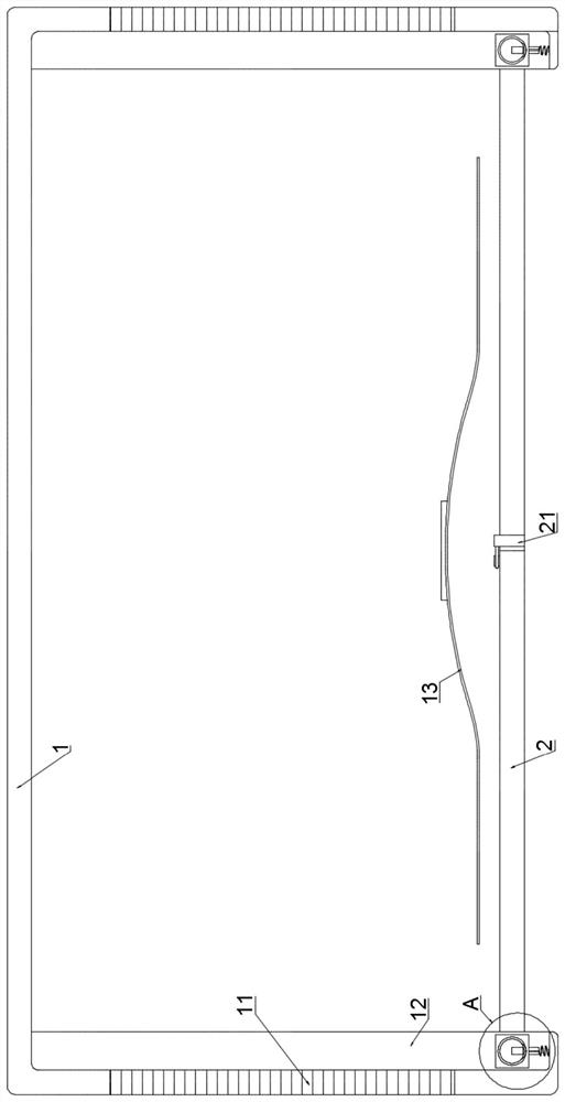
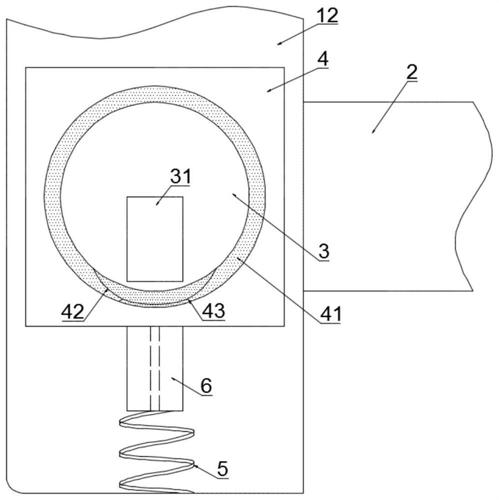
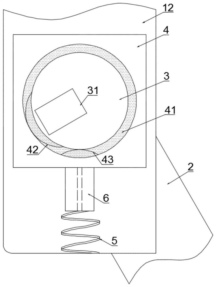
[0026] refer to Figure 1-5 , a magnetic windproof method for a power distribution cabinet, the specific method is as follows:

[0027] S1. During maintenance, during the process of turning and opening the cabinet door 2, the first permanent magnet block 31 and the second permanent magnet block 6 increase the viscosity of the magnetorheological fluid in the first elastic diaphragm 42 and the second elastic diaphragm 43, forming flow resistance , to avoid the rapid rotation of the cabinet door 2 by the impact of wind;

[0028] S2. Turn the cabinet door 2 until it is parallel to both sides of the power distribution cabinet 1, and push the cabinet door 2 into the power...


PUM


Abstract

The invention discloses a magnetomotive windproof method of a power distribution cabinet, and related to the technical field of power distribution cabinets. The power distribution cabinet comprises apower distribution cabinet body and two cabinet doors rotationally connected to the power distribution cabinet body. A padlock is mounted on the adjacent sides of the two cabinet doors; heat dissipation windows are formed in the two sides of the power distribution cabinet; chutes are formed in the two sides of the top and the bottom in the power distribution cabinet; rotating shafts are fixedly connected to one sides, far away from the padlock, of the two cabinet doors; sliding blocks are rotationally connected to the two ends of the two rotating shafts; rotating grooves are formed in the twoends of the two sliding blocks; when the power distribution cabinet is overhauled, after the padlock on the cabinet doors is opened, the two cabinet doors are opened in a rotating mode until the cabinet doors are parallel to the two sides of the power distribution cabinet, the cabinet doors are pushed into the power distribution cabinet along the chute, and therefore the situation that the cabinetdoors are blown by external wind to affect overhauling operation of workers and even injure the arms of the workers can be completely avoided.

Description

technical field [0001] The invention relates to the technical field of power distribution cabinets, in particular to a magnetic windproof method for a power distribution cabinet. Background technique [0002] Road traffic lights, shooting devices, shooting flashes and street lights are generally equipped with power distribution cabinets, and the power distribution cabinets are generally installed directly on the light poles. When the cabinet door is closed, the cabinet door will vibrate under the blowing of the wind force, causing shear force between the cabinet door and the lock, which will accelerate the aging of the lock on the cabinet door and affect the closing effect of the cabinet door; when the cabinet door is opened When the staff is doing maintenance, the cabinet door is easily driven by the wind and hits the staff's arm. The traditional solution is to add a damping device between the cabinet door and the power distribution cabinet. Although this method makes the c...

Claims


Application Information

Patent Timeline
Patent Type & Authority Applications(China)
IPC IPC(8): H02B1/38E05C17/56E05F5/08
CPCE05C17/56E05F5/08H02B1/38
Inventor 杨伟夏春辉陈静
Owner 杨伟
Learn More