Tool bit abrasion monitoring method and tool bit abrasion monitoring system

A monitoring system and cutter head technology, applied in closed-circuit television systems, image data processing, instruments, etc., can solve the problems of high cost, large amount of silicon wafer consumables, and high PM frequency of the machine, achieving simple structure, easy installation, The effect of improving production efficiency

Pending Publication Date: 2020-09-01
SHANGHAI HUALI INTEGRATED CIRCUTE MFG CO LTD
View PDF3 Cites 1 Cited by
  • Summary
  • Abstract
  • Description
  • Claims
  • Application Information

AI Technical Summary

Problems solved by technology

[0007] Because the frequency of CCS measurement is relatively high, the consumption of silicon wafer consumables will be more, and the cost will be higher, and after the silicon wafer is used up, machine PM (equipment maintenance and maintenance) needs to be replaced, which will make the machine PM frequency higher

Method used


Image

  • Tool bit abrasion monitoring method and tool bit abrasion monitoring system
  • Tool bit abrasion monitoring method and tool bit abrasion monitoring system
  • Tool bit abrasion monitoring method and tool bit abrasion monitoring system

Examples


no. 3 example

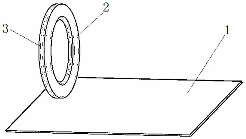
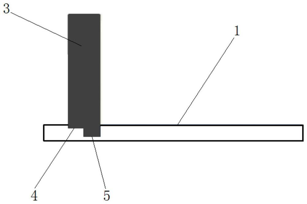
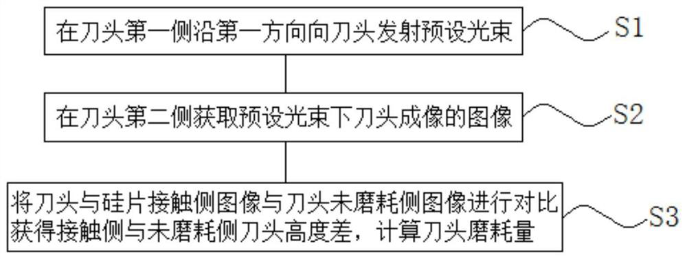
[0063] The third embodiment, such as Figure 4 As shown, the present invention is a kind of cutter head wear monitoring system that is used for Trim process cutter head wear monitoring in BSI technology, comprises:

[0064] The light source 6, which is arranged on the first side of the cutter head, is used to emit a preset beam to the cutter head along the first direction;

[0065] Imaging unit 7, which is arranged on the second side of the cutter head, is used to obtain the image of the cutter head under the preset beam, and output the image of the cutter head to the processing unit; the simplest imaging unit is a backplane and a camera, The photographic equipment shoots the image of the cutter head on the back plate;

[0066] A processing unit 8, which receives the image output by the imaging unit, compares the image of the contact side of the cutter head with the silicon wafer and the image of the unworn side of the cutter head, obtains the height difference between the co...


PUM


Abstract

The invention discloses a tool bit abrasion monitoring method, which is used for tool bit abrasion monitoring in a Trim process in a BSI process, and comprises the following steps of: emitting a preset light beam to a tool bit along a first direction on a first side of the tool bit; acquiring an image imaged by the tool bit under the preset light beam on the second side of the tool bit; comparingthe contact side image of the tool bit and the silicon wafer with the unworn side image of the tool bit to obtain the height difference between the contact side tool bit and the unworn side tool bit,and calculating the abrasion loss of the tool bit; wherein the first direction is perpendicular to the tool bit working face, and the first side of the tool bit is the opposite side of the second sideof the tool bit. The invention further discloses a tool bit abrasion monitoring system. According to the invention, the step of cutting off a specific depth at a specific position by using a tool biton a silicon wafer in the prior art can be reduced, so that the silicon wafer does not need to be consumed, frequent maintenance and replacement of machine equipment are not needed, the tool bit abrasion monitoring cost can be reduced, and the production efficiency is improved.

Description

technical field [0001] The invention relates to the field of semiconductor production and manufacturing, in particular to a tool tip wear monitoring method used for monitoring tool tip wear in a Trim process in a BSI process. The invention also relates to a cutter head wear monitoring system used for monitoring the wear of the cutter head in the Trim process in the BSI process. Background technique [0002] Trim is an important process in the BSI process, which is to cut off a circle of a certain depth and width on the edge of the silicon wafer with a knife head. During the Trim operation, the cutter head will be worn, and when the wear reaches a certain level, it needs to be sharpened to regain a flat cutting surface. Therefore, it is necessary to monitor the wear degree of the cutter head at any time during the Trim operation. The current method of monitoring the wear of the cutter head is CCS (Chopper Cut Setup). This method is to use the cutter head to cut a specific d...

Claims


Application Information

Patent Timeline
Patent Type & Authority Applications(China)
IPC IPC(8): G06T7/00G08B21/24H04N7/18
CPCG06T7/0004H04N7/18G08B21/24
Inventor 曹玉荣李虎
Owner SHANGHAI HUALI INTEGRATED CIRCUTE MFG CO LTD
Why Eureka
Try Eureka