
A high-precision drilling imaging method and device for array acoustic wave scanning

A drilling imaging, high-precision technology, used in earthwork drilling, surveying, wellbore/well components, etc., can solve problems such as low accuracy and distortion of acoustic drilling imaging results, achieve simplified structural components, rich detection data, The effect of significant scientific significance and economic practical value

Active Publication Date: 2021-09-03
INST OF ROCK & SOIL MECHANICS CHINESE ACAD OF SCI
View PDF13 Cites 0 Cited by
  • Summary
  • Abstract
  • Description
  • Claims
  • Application Information

AI Technical Summary

Problems solved by technology

[0005] The purpose of the present invention is to overcome the problem of distortion and low-precision detection of acoustic wave borehole imaging results caused by the misalignment of instrument probes in the past, and propose a high-precision borehole imaging device for array type acoustic wave scanning, and also provide an array type The high-precision drilling imaging method of acoustic scanning realizes real-time correction of different drilling depths and different drilling environmental media, effectively improving the drilling imaging accuracy of acoustic scanning

Method used

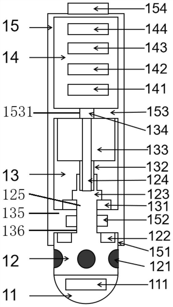
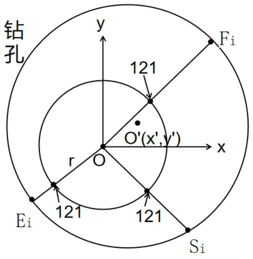

Image

  • A high-precision drilling imaging method and device for array acoustic wave scanning
  • A high-precision drilling imaging method and device for array acoustic wave scanning
  • A high-precision drilling imaging method and device for array acoustic wave scanning

Examples


Embodiment Construction

[0058] Below in conjunction with accompanying drawing and implementation example the present invention is further described:

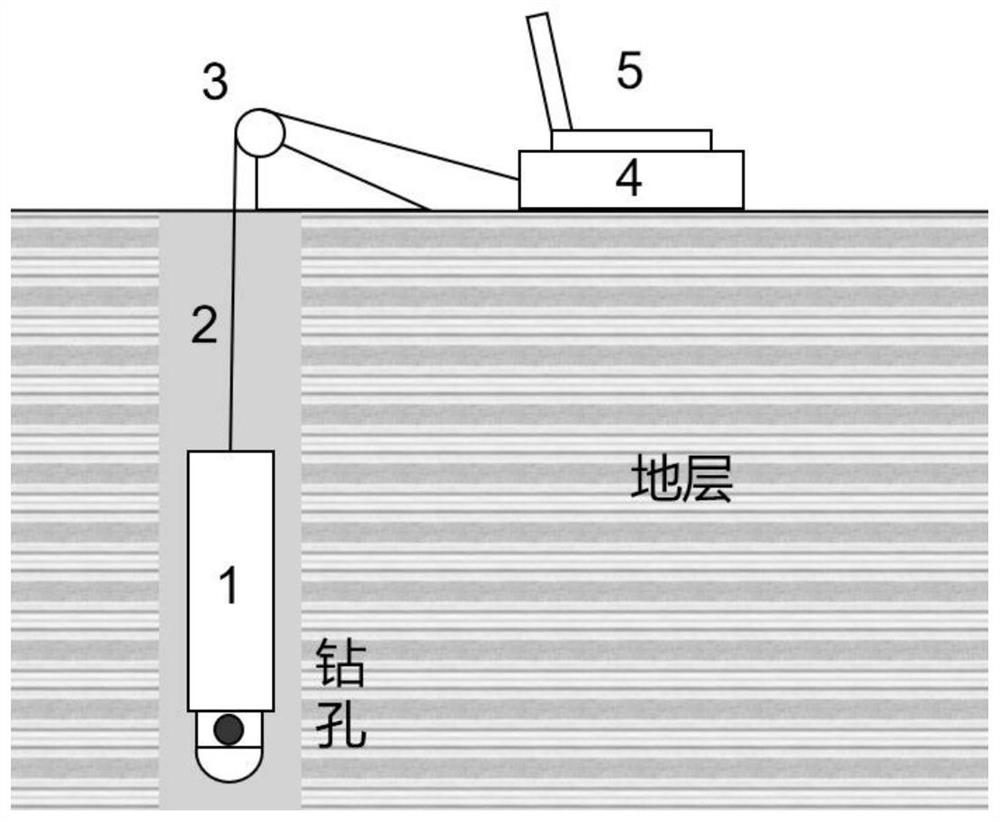
[0059] A high-precision borehole imaging device for array acoustic wave scanning, which mainly includes five parts: an in-hole probe 1, a transmission cable 2, a depth encoder 3, an integrated control box 4, and an industrial computer 5;

[0060] Such as figure 1 As shown, the borehole probe 1 is mainly responsible for collecting data in the borehole. The borehole probe 1 is placed inside the borehole to work. The transmission cable 2 is mainly used to upload the data of the borehole probe 1 to the ground. The depth encoder 3 is mainly used for The depth of the borehole where the probe 1 is located is collected in real time, the depth encoder 3 is usually placed in the borehole, the transmission cable 2 is connected to the integrated control box 4 on the ground, and the integrated control box 4 is used for data demodulation and power supply , the indu...


PUM


Abstract

The invention discloses a high-precision drilling imaging device for array type acoustic wave scanning. The scanning head is located at the bottom of the protective casing, the guide cover is arranged at the bottom of the scanning head, and the protective casing is divided into a circuit module cavity and a scanning power by a positioning platen. The lower part of the scanning head is evenly arranged with N acoustic wave probes in the circumferential direction. The present invention also discloses a high-precision drilling imaging method for array acoustic wave scanning. The present invention utilizes multiple acoustic wave probes to realize the array acoustic wave probe Reasonable arrangement of borehole scanning, using the scanning power chamber to realize the omni-directional acoustic scanning detection of boreholes, forming a high-precision borehole imaging system of array acoustic scanning, and solving the problem of acoustic borehole imaging caused by the misalignment of the instrument probe The problem of distorted results and low-precision detection has achieved rich detection data and strong detection adaptability. It has made breakthroughs and substantial progress in the detection accuracy of borehole imaging, and has significant scientific significance and economic and practical value.

Description

technical field [0001] The present invention relates to the field of geotechnical structure detection devices, in particular to a high-precision borehole imaging device for array-type acoustic wave scanning, and also relates to a high-precision borehole imaging method for array-type acoustic wave scanning, which is applicable to various engineering fields Carry out detailed investigation and detection of the rock mass structure in the geological borehole, obtain the image feature information of the drilled rock mass structure and the structural feature information of the drilled rock mass, and realize the borehole detection of different depths, different sizes and different liquid medium environments . Background technique [0002] Rock mass is a complex geological structure composed of discontinuous structural planes such as fissures, joints, beddings, and faults. For a long time, the research on these discontinuous structural planes constitutes the basis of engineering ge...

Claims


Application Information

Patent Timeline
Patent Type & Authority Patents(China)
IPC IPC(8): E21B47/002E21B47/00E21B47/14
CPCE21B47/00E21B47/14
Inventor 汪进超王川婴韩增强
Owner INST OF ROCK & SOIL MECHANICS CHINESE ACAD OF SCI
Learn More