Cutting tool

A technology of knives and blades, which is applied in the field of knives, can solve the problem of blocking the movement path of the movable parts of the knives, and achieve the effect of reducing functional reliability

Active Publication Date: 2020-09-01
MARTOR
View PDF7 Cites 0 Cited by
  • Summary
  • Abstract
  • Description
  • Claims
  • Application Information

AI Technical Summary

Problems solved by technology

Particles enter the inner space of the housing and, due to particle adhesion, can block the movement path of the movable parts of the tool

Method used


Image

  • Cutting tool
  • Cutting tool
  • Cutting tool

Examples


Embodiment Construction

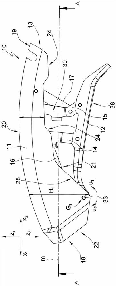
[0058] The tool as a whole is designated by the reference number 10 in the figures.

[0059] The direction x1 points forward with respect to the longitudinal axis m of the tool 10 , the direction x2 points backwards, the direction z1 points upwards and the direction z2 points downwards. The direction y1 points to the left and the direction y2 points to the right with respect to the longitudinal axis m of the tool 10 .

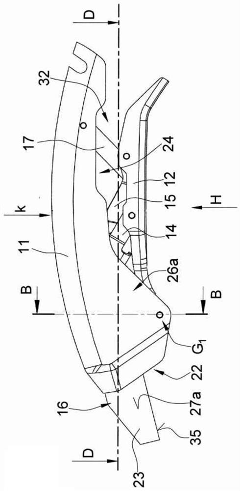
[0060] The tool 10 comprises a first gear part 11 and a second gear part 12 which are embodied in the shape of a housing. The first transmission part 11 and the second transmission part 12 form a pivot hinge G1, so that when the second transmission part 12 is pivoted in direction u1 relative to the first transmission part 11, the tool 10 can be moved from figure 1 movement from the rest position shown to the Figure 3a in the operating position.

[0061] The transmission parts 11 and 12 are part of a transmission 13 which also comprises a rocker arm 14 and a...


PUM


Abstract

The invention relates to a cutting tool (10), comprising a housing and a blade device (16); the blade device includes a blade (23) having at least one cutting edge (35), wherein the blade device (16)and/or the blade protection device can move between at least one rest position and at least one operating position relative to the housing, wherein the housing has at least one opening (22, 24). The present invention is characterized in that the particle flow cross-section of the housing remains substantially constant or increases in the particle (34) flow direction; the particle flow direction isfrom the particle (34) on one end region (18) of the housing into the inlet region (36) in the internal space (25) to the outlet region (37) of the particle (34).

Description

technical field [0001] The invention relates to a knife. Background technique [0002] Such a knife is known from EP 2207649 . The knife comprises a housing and an actuating device, by means of which the blade holder can be moved between a safety position and a cutting position, in which the blade held in the blade holder is arranged relative to the housing in such a way that the user does not Can be injured, in this cutting position the blade protrudes from the housing. [0003] It has been shown that the functional reliability of the knives of the prior art is reduced to complete failure due to the contact of the knives with materials which tend to stick or adhere, such as powder, during the cutting process. Particles get into the housing interior and, due to particle adhesion, can block the movement path of the movable parts of the tool. Contents of the invention [0004] The object of the present invention is to provide a knife which is designed in such a way that p...

Claims


Application Information

Patent Timeline
Patent Type & Authority Applications(China)
IPC IPC(8): B26B5/00B26B1/08
CPCB26B5/002B26B1/08B26B5/003B26B5/001B26B29/02
Inventor M·罗尔巴赫K·亨
Owner MARTOR
Why Eureka
Try Eureka