
Feeding device for thickener and mounting method thereof

A technology of feeding device and thickener, which is applied to the feeding/discharging device of sedimentation tank, separation method, chemical instrument and method, etc. It can improve the utilization rate of tailings, improve the mixing uniformity, and avoid the overflow water running and mixing.

Pending Publication Date: 2020-09-01
CHINA MINMETALS CHANGSHA MINING RES INST
View PDF7 Cites 7 Cited by
  • Summary
  • Abstract
  • Description
  • Claims
  • Application Information

AI Technical Summary

Problems solved by technology

[0006] 1. The flocculant is quantitatively added into the cylinder. Because the moving path of the tailing mortar in the cylinder is short, the flocculant cannot be fully mixed with the tailing slurry in the cylinder, and the flocculation and settlement effect of the tailing mortar is poor.
[0007] 2. The tailing sand at the discharge pipe of the traditional feeding device will directly enter the clarification area of ​​the thickener in disorder, impact the sediment layer, and the fine particle tailing mortar rises with the water, which cannot play the filtering role of the sediment layer, and the overflow water is very easy running around
However, when the particle size of the tailings is too small, the forced dilution will cause serious overflow water running and mixing, which will increase the energy consumption of thickening

Method used


Image

  • Feeding device for thickener and mounting method thereof
  • Feeding device for thickener and mounting method thereof
  • Feeding device for thickener and mounting method thereof

Examples


Embodiment Construction

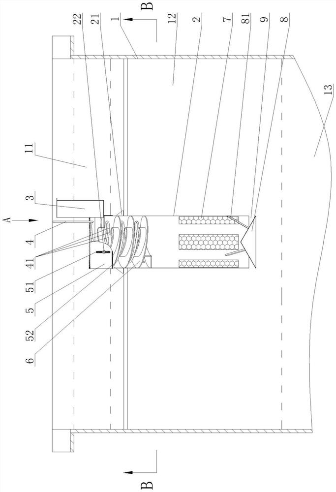
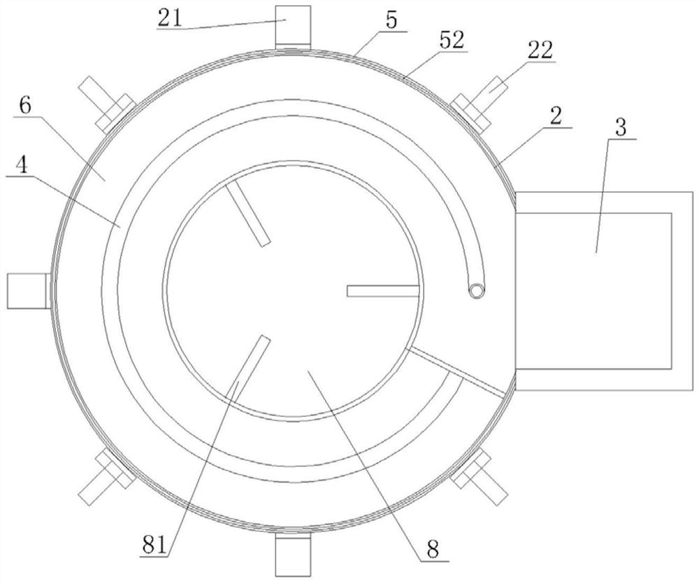
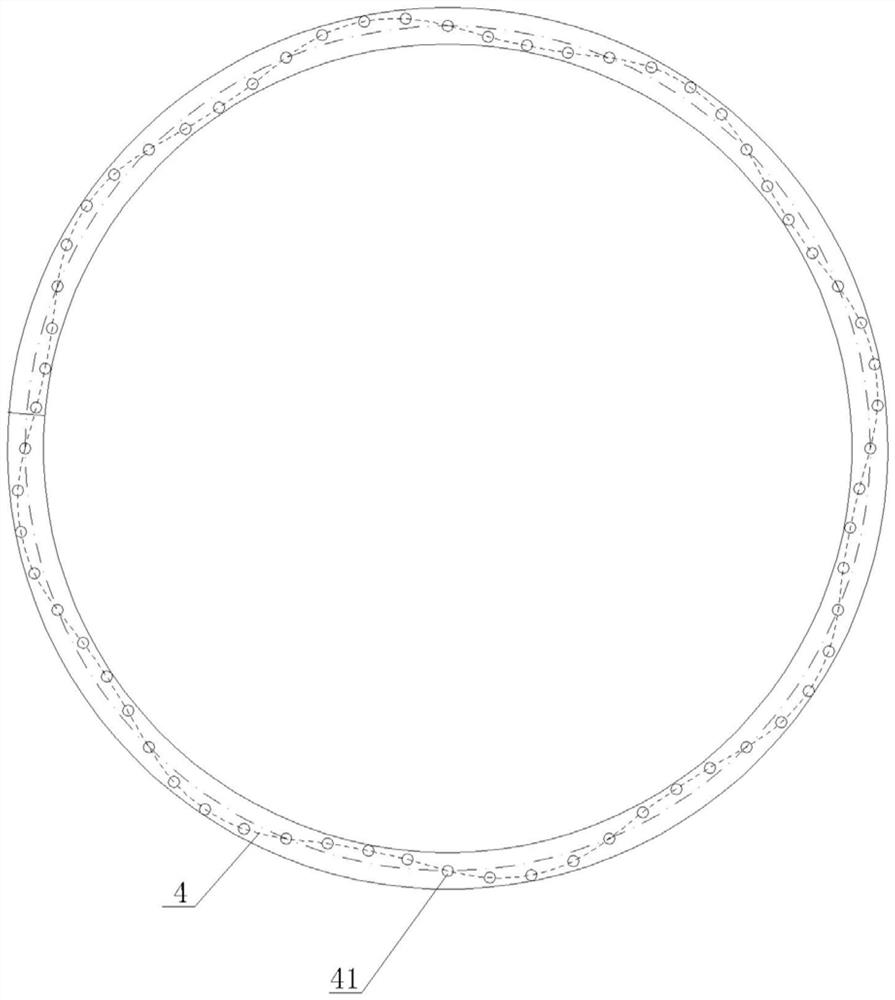
[0042] from Figure 1 to Figure 3 It can be seen that the feeding device for the thickener of the present invention includes a feeding cylinder 2, a feeding trough 3, an adding pipe 4, a self-diluting baffle 5, a spiral guide chute 6, a filter cloth 7 and a conical splitter. Tray 8;

[0043] The feed cylinder 2 is erected in the thickener body 1 through the hanging lugs 21 provided on the cylinder wall. The interior of the thickener body 1 includes a clarification zone 11, a settling zone 12 and a compression zone 13 arranged sequentially from top to bottom. The top surface of the feeding barrel 2 is located at the lower boundary of the clarification zone 11, and four screws 22 arranged radially along the feeding barrel 2 are welded on the wall of the feeding barrel 2 top, and the four screws 22 are arranged along the feeding barrel 2. Evenly distributed in the circumferential direction;

[0044] The feeding chute 3 is welded on the feeding cylinder 2 between two adjacent sc...


PUM


Abstract

The invention discloses a feeding device for a thickener and a mounting method of the feeding device. The feeding device comprises a feeding cylinder, a feeding groove and an adding pipe which are arranged in the body of the thickener; wherein the thickener body internally comprises a clarification area, a sedimentation area and a compression area, the top surface of the feeding cylinder is not higher than the sedimentation area, a self-dilution baffle is connected to the top of the feeding cylinder in a height-adjustable surrounding and sealing manner, the top of the self-dilution baffle is arranged in the clarification area, and the two end parts of the self-dilution baffle are in sealed butt joint with the side wall of the feeding groove; a spiral guide groove is formed in the upper endsection of the feeding cylinder; a discharge port of the feeding groove is communicated with an upper port of the spiral guide groove; a plurality of pieces of filter cloth are uniformly distributedon the cylinder wall of the lower end section of the feeding cylinder along the circumference and are arranged in the compression area; the bottom of the feeding cylinder is connected with a conical material distribution disc, and the conical surface of the conical material distribution disc and the bottom surface of the feeding cylinder are vertically arranged in a spaced mode to form a circumferential discharging port. According to the invention, a flocculating agent and a tailing slurry can be fully mixed in the feeding device, and better tailing slurry treatment capacity is achieved.

Description

technical field [0001] The invention relates to the technical field of mine solid waste filling, in particular to a feeding device for a thickener and an installation method thereof. Background technique [0002] The filling mining method belongs to the artificial support mining method. In the mine room or ore block, as the mining face advances, the filling material is sent to the goaf to manage the ground pressure, control the collapse of the surrounding rock and the movement of the ground surface, and protect the formed filling body down for recovery. The filling mining method has been widely used in underground mines due to its advantages of high recovery rate, safe operation, and protection of surface features. [0003] The commonly used filling aggregate in metal mines is tailings (or tailings, including graded tailings and full tailings). The main filling process is to pump the tailings from the dressing plant with a low mass concentration (generally 10-20%, 40-45% ...

Claims


Application Information

Patent Timeline
Patent Type & Authority Applications(China)
IPC IPC(8): B01D21/00B01D21/01B01D21/24
CPCB01D21/0042B01D21/01B01D21/2405B01D21/0012
Inventor 郑伯坤周贺彬尹旭岩黄腾龙张要贺
Owner CHINA MINMETALS CHANGSHA MINING RES INST
Learn More