
Rotor core and motor

A rotor core and segmented core technology, which is applied in the field of rotor core and motor equipment, can solve the problems of motor torque/power density reduction, low torque/power density, increase electromagnetic ineffective parts, etc., and improve torque ripple and NVH characteristics, improved torque/power density, and reduced air gap unevenness

Pending Publication Date: 2020-08-28
CSR ZHUZHOU ELECTRIC CO LTD
View PDF0 Cites 4 Cited by
  • Summary
  • Abstract
  • Description
  • Claims
  • Application Information

AI Technical Summary

Problems solved by technology

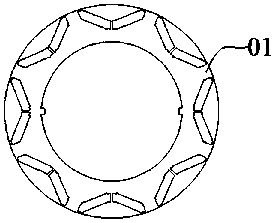
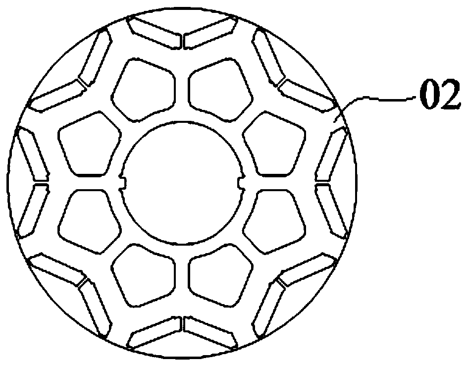
[0004] For the first existing iron core structure 01, it is necessary to add a rotor bracket component. During mass production, the brackets are all cast, resulting in uneven thickness around the periphery, difficult to correct the dynamic balance, and the coaxiality of the outer circle of the bracket and the rotor The coaxiality fit requires high precision, otherwise it will lead to uneven air gap of the rotor, resulting in unbalanced magnetic pull, resulting in problems such as torque ripple and NVH difference; for the second existing iron core structure 02, when the rotor outer diameter is large When the core is long, the weight of the load-bearing structure increases, which increases the electromagnetic ineffective part, resulting in a large weight of the whole machine, low torque / power density, and power consumption for the whole vehicle
[0005] Therefore, how to provide a rotor core that solves the problems of increased weight and reduced motor torque / power density when the outer diameter and axial length of the rotor are large is a technical problem urgently needed by those skilled in the art.

Method used


Image

  • Rotor core and motor
  • Rotor core and motor
  • Rotor core and motor

Examples


Embodiment Construction

[0027] The following will clearly and completely describe the technical solutions in the embodiments of the present invention with reference to the accompanying drawings in the embodiments of the present invention. Obviously, the described embodiments are only some, not all, embodiments of the present invention. Based on the embodiments of the present invention, all other embodiments obtained by persons of ordinary skill in the art without making creative efforts belong to the protection scope of the present invention.

[0028] In order to enable those skilled in the art to better understand the solution of the present invention, the present invention will be further described in detail below in conjunction with the accompanying drawings and specific embodiments.

[0029] Please refer to Figure 1 to Figure 6 ,in, figure 1 Schematic diagram of the structure of the rotor core provided by the embodiment of the present invention, figure 2 It is a structural schematic diagram o...


PUM


Abstract

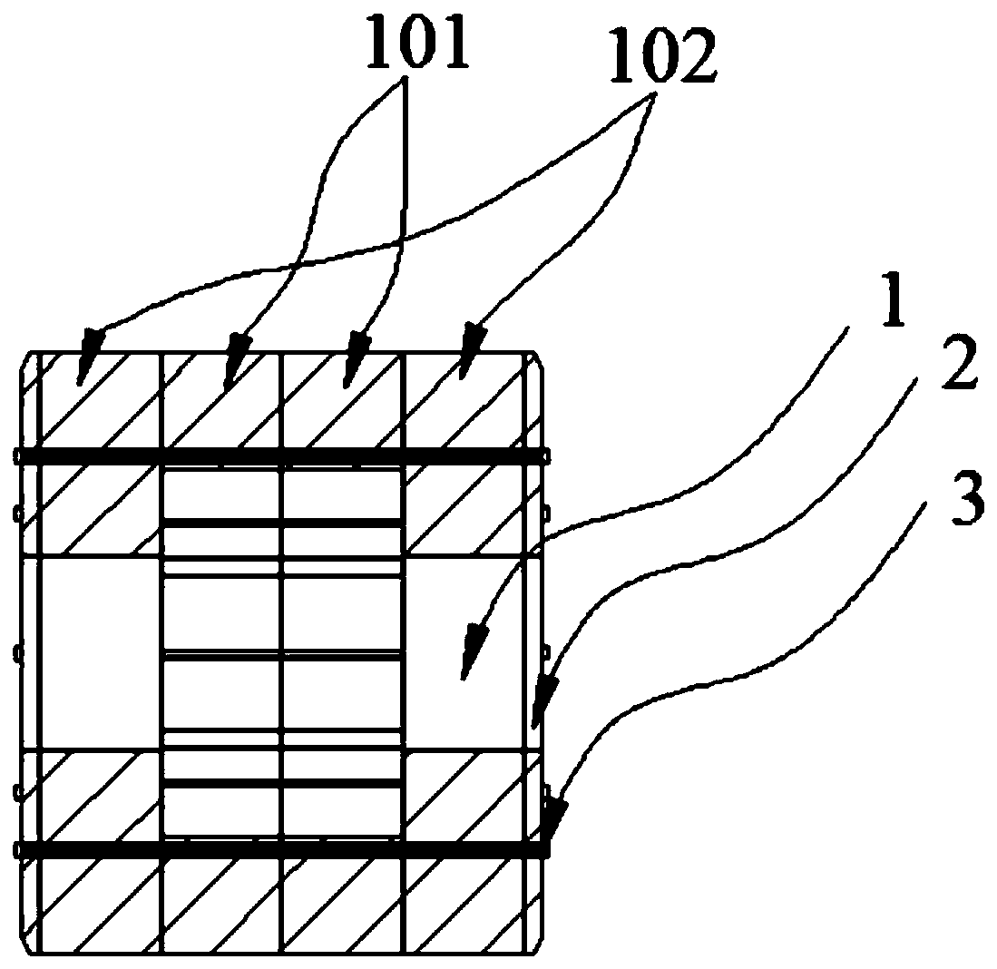
The invention discloses a rotor core and a motor. The rotor iron core comprises magnetic steel baffles arranged at the two ends, a plurality of sections of first segmented iron cores and a plurality of sections of second segmented iron cores are fixedly arranged between the magnetic steel baffles, matching of the rotor iron core and a rotating shaft is achieved through the first segmented iron cores, and weight reduction of the rotor iron core is achieved through the second segmented iron cores. According to the rotor core, the total weight of the motor is directly reduced, the torque / power density is improved, the unbalance amount generated by a support structure is reduced, the air gap non-uniformity is reduced, and the torque pulsation and the NVH characteristic of the motor are improved; indirectly, support dies are reduced, matching of the support and the rotor core is improved, air gap non-uniformity caused by different coaxiality is reduced, the process requirement is simplified, and the production efficiency is improved.

Description

technical field [0001] The invention relates to the technical field of motor equipment, in particular to a rotor core. It also relates to a motor. Background technique [0002] With the development of new energy vehicles and the lightweight of electric vehicles, the requirements for high torque / power density motors are becoming more and more stringent. In addition to improving electromagnetic design and other aspects, structural improvements can also be made. [0003] In the current new energy vehicles, the rotor core of the motor mainly adopts such as figure 2 and image 3 Two structures. in, figure 2 The first existing core structure 01 with a bracket is suitable for rotor cores with large outer diameter (over φ260mm) and long core length (over 150mm); image 3 The second existing core structure 02 has weight-reducing holes, which is suitable for rotor cores with small outer diameter (within φ260mm) and short core length (within 150mm). [0004] For the first existin...

Claims


Application Information

Patent Timeline
Patent Type & Authority Applications(China)
IPC IPC(8): H02K1/27H02K1/28
CPCH02K1/2766H02K1/28
Inventor 唐小春于冰董江东关磊欧晓辉许时杰黄绍枝张帅王振
Owner CSR ZHUZHOU ELECTRIC CO LTD
Learn More