
Point cloud error calculation method

An error calculation and point cloud technology, applied in the field of three-dimensional measurement, can solve problems such as time-consuming, point cloud data errors, and low efficiency

Active Publication Date: 2020-08-28
易思维(杭州)科技有限公司
View PDF6 Cites 2 Cited by
  • Summary
  • Abstract
  • Description
  • Claims
  • Application Information

AI Technical Summary

Problems solved by technology

[0002]With the continuous development of modern manufacturing industry, reverse engineering technology has been widely researched and applied; among them, 3D scanning modeling is a common reverse technology, and its Three-dimensional scanning measurement equipment is used to measure the entities in the scene to obtain discrete point cloud data; due to the accuracy error of the measurement equipment itself and the inevitable electromagnetic interference, there are errors (noise) in the point cloud data; in order to calculate the error, evaluate the point For cloud data, it is often necessary to use the CAD digital model of the measured entity as a reference for error calculation; the digital model is usually expressed in the form of a mesh surface, which includes graphic patches, vertices and vertex sequences; for this reason, the existing method calculates The method of point cloud error is to calculate the directed distance between each point in the measured point cloud and its nearest neighbor graphic patch. When calculating, firstly, all graphic patches are used as candidate objects to calculate one by one, and the nearest neighbor is obtained after sorting. Graphical patch; this calculation method has the problems of long time consumption and low efficiency

Method used


Image

  • Point cloud error calculation method
  • Point cloud error calculation method
  • Point cloud error calculation method

Examples


Embodiment Construction

[0033] The technical solutions of the present invention will be described in detail below in conjunction with the accompanying drawings and specific embodiments.

[0034] A point cloud error calculation method, the grid surface of the digital model of the object to be measured is recorded as the theoretical grid surface, the normal vector of any graphic surface in the theoretical grid surface is obtained, and the single vertex of any graphic surface is recorded as the vertex V;

[0035] The theoretical mesh surface is obtained by meshing the digital model of the object to be measured; the graphic surface is a triangular surface or a rectangular surface.

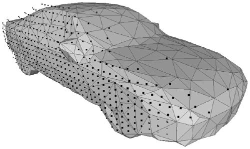
[0036] Such as figure 1 As shown, in this embodiment, taking the triangle facet as an example, the vertex V is the vertex of the triangle facet;

[0037] Use the 3D scanning device to obtain the 3D point cloud on the surface of the object to be measured, and record it as the measured point cloud; establish the topological r...


PUM


Abstract

The invention discloses a point cloud error calculation method, which processes an actually tested point cloud and a theoretical grid curved surface, comprising the following steps: searching an adjacent point set of a vertex V through employing a nearest neighbor search method; calculating the Euclidean distance between the vertex V and the centroid of the first graphic patch; constructing a cylindrical search space by taking the vertex V as a cylindrical geometric center; traversing each point in the adjacent point set, screening out each reference point from the adjacent point set, and storing the reference points as a reference point set; solving a centroid C of the reference point set, and recording a directed distance L between the centroid C and the vertex V as a point cloud error;and traversing each vertex V in the theoretical grid curved surface to obtain a point cloud error between a reference point set corresponding to each vertex V and the theoretical grid curved surface.The point cloud error calculation method can quantify the error between the actually tested point cloud and the theoretical grid curved surface of the object to be measured, and can be used for evaluating the quality of actually tested point cloud data.

Description

technical field [0001] The invention relates to the field of three-dimensional measurement, and specifically relates to a point cloud error calculation method. Background technique [0002] With the continuous development of modern manufacturing industry, reverse engineering technology has been widely researched and applied; among them, 3D scanning modeling is a common reverse technology, which uses 3D scanning measurement equipment to measure the entities in the scene and obtain discrete point cloud data; due to the accuracy error of the measuring equipment itself and the inevitable electromagnetic interference, there are errors (noise) in the point cloud data; in order to calculate the error and evaluate the point cloud data, it is often necessary to use the CAD digital model of the measured entity as a reference , to calculate the error; the digital model is usually expressed in the form of a mesh surface, which includes a graphic patch, vertex and vertex sequence; for th...

Claims


Application Information

Patent Timeline
Patent Type & Authority Applications(China)
IPC IPC(8): G06T17/20G06T17/10G06T17/00
CPCG06T17/20G06T17/10G06T17/005
Inventor 庄洵何莎徐航
Owner 易思维(杭州)科技有限公司
Learn More