
Burner for gas stove and gas stove

A gas stove and burner technology, applied in the field of stoves, can solve the problems of pressure loss, sudden drop in speed, uneven distribution of burner flames, etc., and achieve the effects of increasing mixing time, improving gas mixing effect, and eliminating pressure loss

Pending Publication Date: 2020-08-28
刘迪
View PDF0 Cites 4 Cited by
  • Summary
  • Abstract
  • Description
  • Claims
  • Application Information

AI Technical Summary

Problems solved by technology

On the one hand, this structure will suddenly increase the cross-sectional area of ​​the flow path of the high-speed mixed gas injected by the ejector, and the speed will drop suddenly, causing a large pressure loss; on the other hand, it will cause the flow velocity distribution of the mixed gas flowing out of the mixed gas chamber. Inhomogeneity, which in turn leads to uneven flame distribution of the burner

Method used


Image

  • Burner for gas stove and gas stove
  • Burner for gas stove and gas stove
  • Burner for gas stove and gas stove

Examples


Embodiment Construction

[0029] In order to enable those skilled in the art to better understand the solution of the present application, the technical solution in the embodiment of the application will be clearly and completely described below in conjunction with the accompanying drawings in the embodiment of the application. Obviously, the described embodiment is only It is an embodiment of a part of the application, but not all of the embodiments. Based on the embodiments in this application, all other embodiments obtained by persons of ordinary skill in the art without creative efforts shall fall within the scope of protection of this application.

[0030] It should be noted that the terms "comprising" and "having" in the specification and claims of the present application and the above-mentioned drawings and any variations thereof are intended to cover a non-exclusive inclusion, for example, a system comprising a series of units , products or equipment are not necessarily limited to those element...


PUM


Abstract

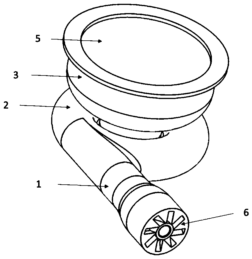
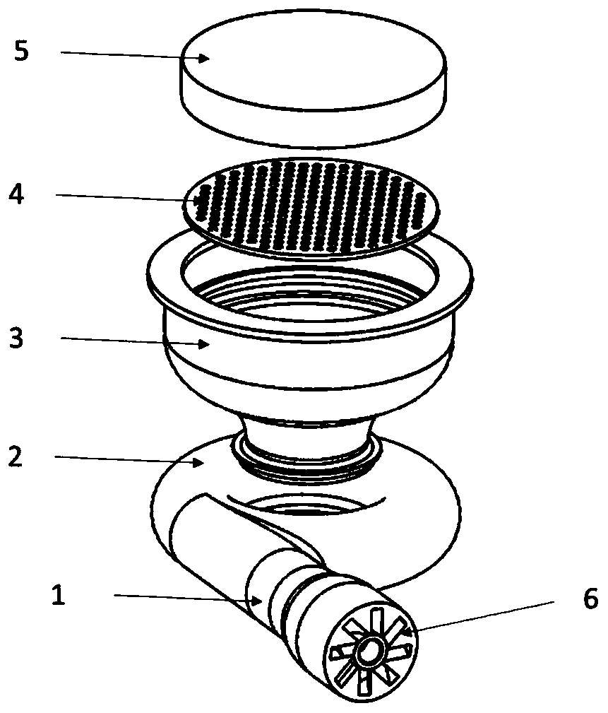
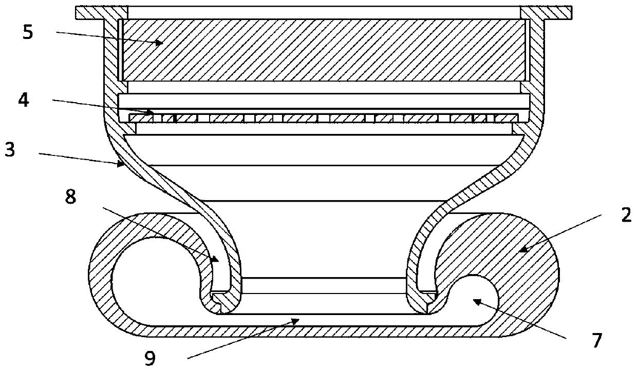
The invention relates to the technical field of stoves, in particular to a burner for a gas stove, and further relates to the gas stove comprising the burner. The burner for the gas stove comprises avolute, an ejector and a pot body; a gas mixing chamber with a volute flow channel is formed in the volute, a concave part with a closed bottom and an open top is formed in the middle of the volute, and a gas hole communicating with the volute flow channel and the concave part is formed in the volute; an air outlet in the ejector communicates with an air inlet in the gas mixing chamber, and the air outlet direction of the ejector is tangent to the volute flow channel; and the inlet end of the pot body is arranged in the concave part in a matched mode, an inlet in the pot body communicates withthe air hole, and an anti-backfire pore plate and a foam metal heating body are sequentially arranged at the outlet end of the pot body. According to the burner, the gas outlet direction of the ejector is tangent to the volute flow channel in the gas mixing chamber, so that the pressure loss caused by sudden expansion of the flow channel between the ejector and the gas mixing chamber is eliminated; and the gas mixing time is prolonged through the gas mixing chamber with the volute flow channel, so that the gas mixing effect is improved.

Description

technical field [0001] The present application relates to the technical field of stoves, in particular, to a burner for a gas stove, and to a combustion stove including the burner. Background technique [0002] At present, in the field of kitchen stoves, the structure of the burner for gas stove generally adopts a circular or annular gas mixing chamber, and the ejector is usually connected with the gas mixing chamber along the radial direction of the gas mixing chamber. On the one hand, this structure will suddenly increase the cross-sectional area of ​​the flow path of the high-speed mixed gas injected by the ejector, and the speed will drop suddenly, causing a large pressure loss; on the other hand, it will cause the flow velocity distribution of the mixed gas flowing out of the mixed gas chamber. Uneven, which in turn leads to uneven flame distribution of the burner. Contents of the invention [0003] In order to solve the above technical problems, the present applicat...

Claims


Application Information

Patent Timeline
Patent Type & Authority Applications(China)
IPC IPC(8): F23D14/02F23D14/64F23D14/26F23D14/82F24C3/08
CPCF23D14/02F23D14/26F23D14/64F23D14/82F24C3/085
Inventor 刘迪
Owner 刘迪
Learn More