Water pump convenient for exhausting

A water pump and pump body technology, which is applied to the components of the pumping device for elastic fluid, pump, pump control, etc., can solve the problems of affecting pump efficiency, inconvenience, time-consuming and laborious, etc. Variable Adjustment Simple Effects

Inactive Publication Date: 2020-08-28
陈艳艳
View PDF0 Cites 0 Cited by
  • Summary
  • Abstract
  • Description
  • Claims
  • Application Information

AI Technical Summary

Problems solved by technology

[0003] 1. The existing centrifugal water pump can only change the displacement of the pump by adjusting the speed, which will not only affect the efficiency and head of the pump, but also need a speed regulating mechanism to control
Due to the high cost of speed regulating mechanisms such as frequency converters, when different flow rates are required, it is now widely used to control them by changing the pipeline characteristics through throttle valves, resulting in a lot of energy waste;
[0004] 2. The water pump in the prior art needs to fill the pump casing with water before pumping water, and empty the air in the pump casing, so that the impeller of the water pump rotates to drive the liquid to generate centrifugal force, so that the water inlet of the pump generates negative pressure to suck the liquid into , a positive pressure is generated at the water outlet of the pump to discharge the liquid. If there is air in the pump, since the density of the air is less than that of the liquid, the impeller drives the air to rotate and cannot generate centrifugal force, and the pump cannot work. As we all know, the work of filling the pump with water is Very burdensome, time-consuming and inconvenient

Method used


Image

  • Water pump convenient for exhausting
  • Water pump convenient for exhausting
  • Water pump convenient for exhausting

Examples


Embodiment Construction

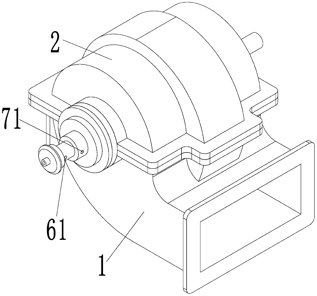
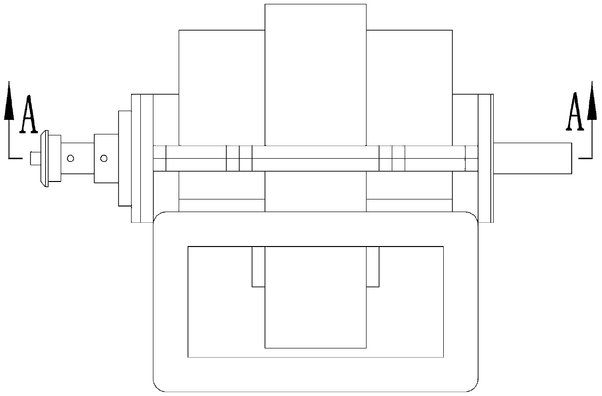
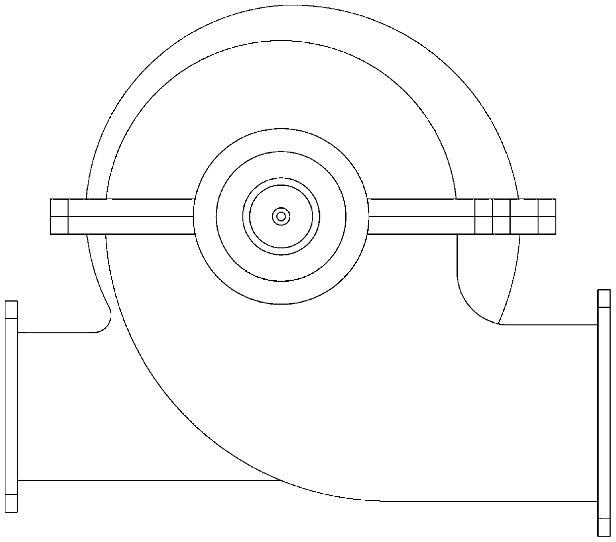
[0028] see Figure 1-11 As shown, a water pump that is convenient for exhausting includes a pump body 1, a pump chamber is arranged in the pump body 1, a left partition 1a and a right partition 1b are arranged side by side in the pump chamber, and the pump chamber is internally A left chamber 1c is formed between the left partition 1a and the left side wall of the pump chamber, a right chamber 1d is formed between the right partition 1b and the right side wall of the pump chamber, and a right chamber 1d is formed between the left partition 1a and the right partition 1b. The impeller chamber 1e is formed between them; the side of the pump body 1 is provided with an outlet pipe 1f communicating with the impeller chamber 1e, and an inlet pipe 1g communicating with the left chamber 1c and the right chamber 1d; the right side of the pump body 1 The side rotation is connected with the power shaft 3 whose left end extends into the impeller chamber 1e, and the impeller assembly is arr...


PUM


Abstract

The invention discloses a water pump convenient for exhausting. The water pump comprises a pump body, wherein a pump cavity is arranged in the pump body, a left partition plate and a right partition plate are arranged in the pump cavity side by side, and a left chamber, a right chamber and an impeller cavity are arranged in the pump cavity; a water outlet pipeline and a water inlet pipeline are arranged on the side surface of the pump body; the right side of the pump body is rotatably connected to a power shaft, and an impeller assembly is arranged on the power shaft in the impeller cavity; the left side of the pump body is slidably connected to an adjusting rod, and the adjusting rod is coaxial to the power shaft; a piston hole is arranged in the adjusting rod, a plunger is arranged at the left end of the power shaft, a pump liquid cavity is formed between the left end of the plunger and the left end of the piston hole in the piston hole, a liquid inlet hole is arranged in the adjusting rod, and a liquid outlet hole is arranged in the plunger and the power shaft; and a liquid inlet one-way valve is arranged in the liquid inlet hole, and a liquid outlet one-way valve is arranged inthe liquid outlet hole. The water pump convenient for exhausting not only has a simple structure but also can quickly fill the pump cavity with water to achieve exhausting.

Description

technical field [0001] The invention belongs to the technical field of centrifugal pumps, in particular to a variable variable centrifugal pump. Background technique [0002] A centrifugal water pump is a machine that transports or pressurizes a liquid. It transmits the mechanical energy of the prime mover or other external energy to the liquid to increase the energy of the liquid. It is mainly used to transport liquids including water, oil, acid and alkali, emulsion, suspension, etc. Emulsions and liquid metals, etc., can also transport liquids, gas mixtures, and liquids containing suspended solids; the technical parameters to measure the performance of centrifugal pumps include flow rate, suction lift, head, shaft power, water power, efficiency, etc. There are following two problems in the centrifugal water pump of prior art: [0003] 1. The existing centrifugal water pump can only change the displacement of the pump by adjusting the speed, which will not only affect the ...

Claims


Application Information

Patent Timeline
Patent Type & Authority Applications(China)
IPC IPC(8): F04D29/00F04D9/00F04D15/00F04D29/42F04D1/00
CPCF04D1/00F04D9/00F04D9/006F04D15/00F04D29/007F04D29/426
Inventor 李来滨邵建国
Owner 陈艳艳
Why Eureka
Try Eureka