
Point switch retention force tester

A holding force and tester technology, applied in force/torque/work measuring instruments, instruments, measuring devices, etc., can solve the technical problems that cannot be solved in the test, achieve good anti-slip effect, and facilitate the measurement of holding force and device. Overall stable effect

Inactive Publication Date: 2020-08-28
OPERATIONS BRANCH SUZHOU RAIL TRANSIT GRP CO LTD
View PDF0 Cites 1 Cited by
  • Summary
  • Abstract
  • Description
  • Claims
  • Application Information

AI Technical Summary

Problems solved by technology

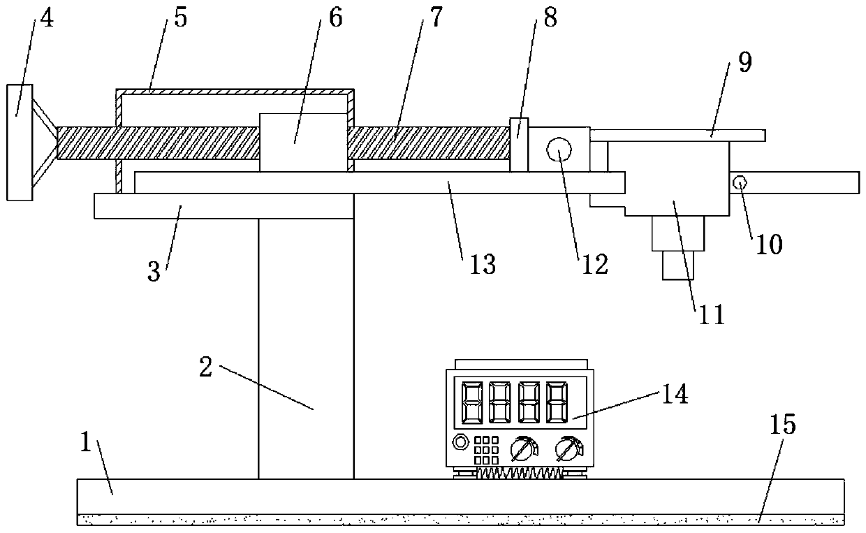
[0004] Based on the fact that a switch machine holding force tester cannot solve the technical problem of testing the core data control panel holding force in S700K switch machine maintenance, the present invention proposes a switch machine holding force tester

Method used


Image

  • Point switch retention force tester
  • Point switch retention force tester
  • Point switch retention force tester

Examples


Embodiment 1

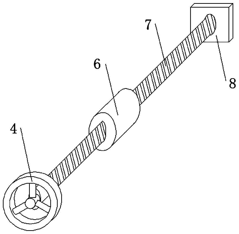
[0023] refer to Figure 1-2 , a switch machine holding force tester, comprising a base plate 1, a base 2 is fixed on the top outer wall of the base plate 1 by bolts, a support plate 3 is fixed on the top outer wall of the base 2 by bolts, and a support plate 3 is fixed on the top outer wall of the support plate 3 by bolts The nut guard 5 is fixed, the top outer wall of the support plate 3 is fixed with a main shaft 13 by bolts, and one end of the main shaft 13 is located inside the nut guard 5, and a pushing mechanism is provided on one side of the outer wall of the nut guard 5 A pressure sensor 12 is slidably clamped on one side of the outer wall of the main shaft 13, and a test piece 11 is slidably clamped at one end of the main shaft 13 close to the pressure sensor 12, and a digital display dynamometer 14 is fixed on the top outer wall of the bottom plate 1 by bolts. , the signal output end of the pressure sensor 12 is connected with the signal input end of the digital disp...

Embodiment 2

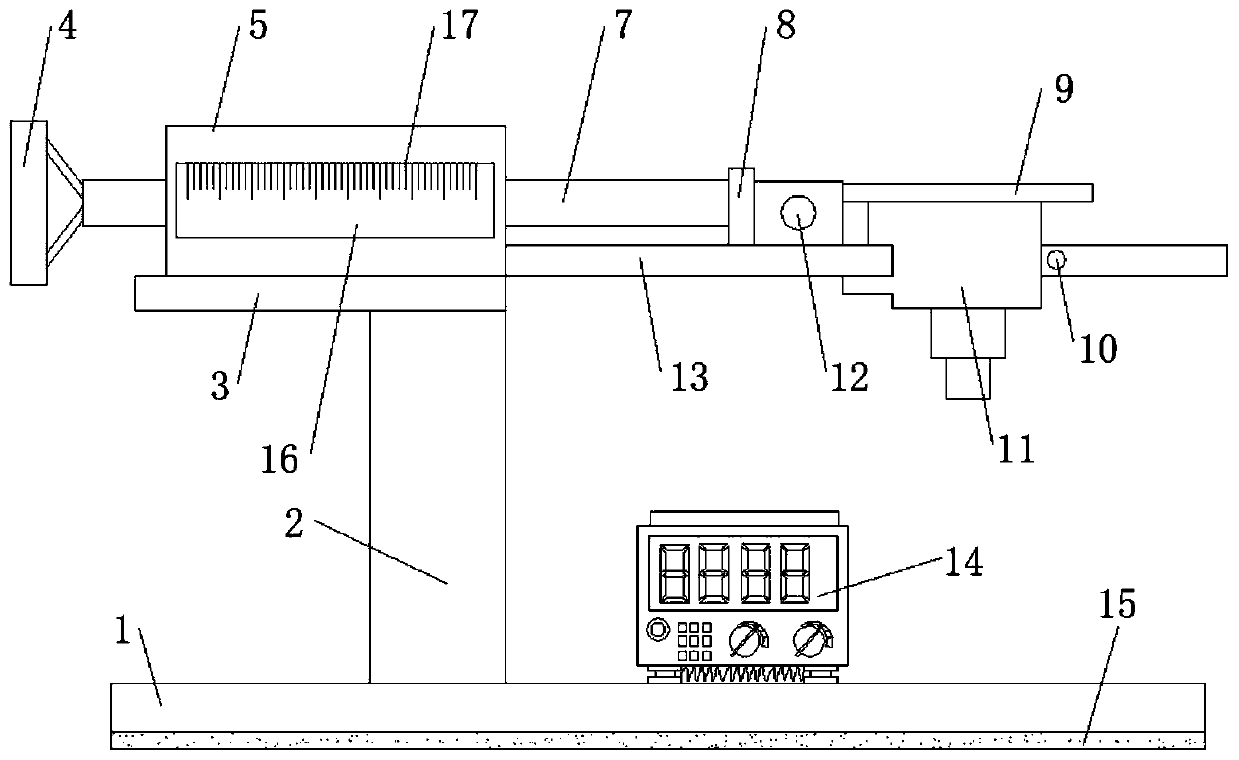
[0027] refer to image 3 , a switch machine holding force tester. Compared with Embodiment 1, this embodiment has an installation opening on one side of the mother guard plate 5, and an observation window 16 is clamped on the inner wall of the installation opening. The observation window Scale marks 17 are engraved on one side outer wall of 16.

[0028] During use, there is observation window 16 on the side outer wall of silk mother guard plate 5, and scale mark 17 is arranged, convenient staff watches how much distance hand wheel 4 shakes and advances.


PUM


Abstract

The invention discloses a point switch retention force tester. The problem that the retention force of a core data control panel of an S700K point switch cannot be tested in the maintenance process issolved. The point switch retention force tester in the scheme comprises a bottom plate; a base is fixed to the outer wall of the top of the bottom plate through bolts; a supporting plate is fixed tothe outer wall of the top of the base through bolts; a nut protection plate is fixed to the outer wall of the top of the supporting plate through bolts; a main shaft is fixed to the outer wall of thetop of the supporting plate through bolts; one end of the main shaft is located in the nut protection plate; a pushing mechanism is arranged on the outer wall of one side of the nut protection plate;and a pressure sensor is slidably connected to the outer wall of one side of the main shaft in a clamped mode. Lead screw transmission serves as a main body, the control panel is pushed to move horizontally, the pressure sensor is connected between the lead screw transmission and the control panel in series to measure the retention force of the control panel, retention force data are accurately tested, and corresponding maintenance and adjustment on the retention force in the maintenance process are facilitated.

Description

technical field [0001] The invention relates to the technical field of switch machine maintenance, in particular to a switch machine holding force tester. Background technique [0002] The switch machine refers to the important signal infrastructure equipment used to reliably change the position of the turnout, change the opening direction of the turnout, lock the tip rail of the turnout, and reflect the position of the turnout. It can well ensure driving safety, improve transportation efficiency, and improve the safety of driving personnel The S700K switch machine is one of them, and a switch machine retention tester is required for its maintenance. [0003] At present, most of the existing switch machine retention testers on the market have the following deficiencies in the process of use: they cannot solve the problem of testing the core data control panel retention of the S700K switch machine maintenance, In summary, most of the existing switch machine holding force tes...

Claims


Application Information

Patent Timeline
IPC IPC(8): B61L5/00G01L5/00
CPCB61L5/00G01L5/00
Inventor 卢里成李新谈逸文尚峰韩洪波周顺凯金镒邱文强吴杰陶冶吴冕周磊吴豹
Owner OPERATIONS BRANCH SUZHOU RAIL TRANSIT GRP CO LTD
Learn More