A demoulding device for smooth floor tiles for construction engineering

A demoulding device and construction engineering technology, applied in the direction of unloading device, manufacturing tools, etc., can solve the problems of low work efficiency, long time-consuming, labor-intensive, etc.

Inactive Publication Date: 2021-07-06
安徽邦龙建业有限公司
View PDF4 Cites 0 Cited by
  • Summary
  • Abstract
  • Description
  • Claims
  • Application Information

AI Technical Summary

Problems solved by technology

[0006] In order to overcome the disadvantages that the above-mentioned method takes a long time to operate, the work efficiency is low, and manual demoulding is required during operation, which is relatively labor-intensive, the technical problem to be solved by the present invention is to provide a method that can improve work efficiency. , and a labor-saving demoulding device for smooth floor tiles for construction projects

Method used


Image

  • A demoulding device for smooth floor tiles for construction engineering
  • A demoulding device for smooth floor tiles for construction engineering
  • A demoulding device for smooth floor tiles for construction engineering

Examples


Embodiment 1

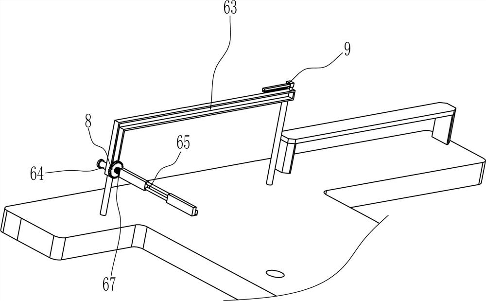
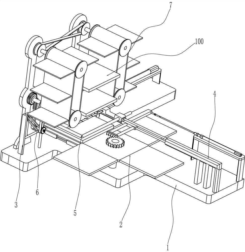
[0025] A kind of demoulding device for smooth floor tiles for construction engineering, such as figure 1 , figure 2 , image 3 with Figure 5 As shown, it includes a base 1, a placement plate 2, a first guide rail 3 and a guide sleeve 4, the middle of the top of the base 1 is rotatably connected to the placement plate 2, the left side of the top of the base 1 is connected to the first guide rail 3, and the right side of the top of the base 1 The guide sleeve 4 is connected, and also includes a sliding assembly 5 and a moving assembly 6 , the sliding assembly 5 is provided between the guide sleeve 4 and the base 1 , and the moving assembly 6 is provided between the placing plate 2 and the base 1 .

[0026] The sliding assembly 5 includes a first air cylinder 51, a first sliding frame 52, a second sliding frame 53 and an elastic member 54. The first air cylinder 51 is mounted on the rear right side of the base 1, and the guide sleeve 4 is slidably connected with a first slidi...

Embodiment 2

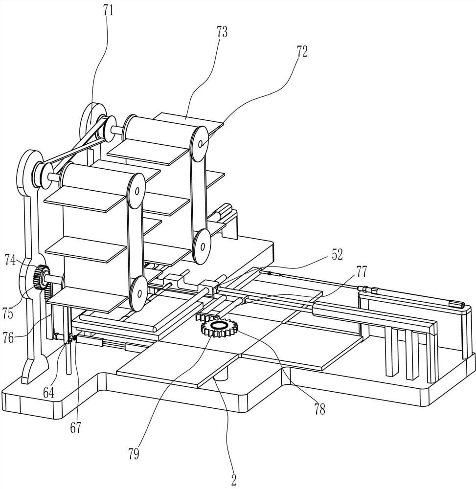
[0030] On the basis of Example 1, such as Figure 4 As shown, it also includes a feeding assembly 7, and the feeding assembly 7 includes a mounting frame 71, a conveyor belt 72, a connecting plate 73, a first one-way clutch 74, a first transmission gear 75, a spur rack 76, a transmission rack 77, the second transmission gear 78 and the second one-way clutch 79, two mounting frames 71 are connected on the left side of the top of the base 1, and the two mounting frames 71 are arranged front and rear, and the conveyor belt 72 is connected with the rotary type on the mounting frame 71, and the two mounting frames 71 are connected with each other. Two conveyor belts 72 are connected by cross-transmission between belts and pulleys, and there are many connecting plates 73 evenly spaced on the conveyor belt 72. The positions of the connecting plates 73 on the two conveyor belts 72 are corresponding. The first one-way clutch 74 is installed, the first one-way clutch 74 is connected wit...


PUM


Abstract

The invention relates to a demoulding device, in particular to a demoulding device for smooth floor tiles used in construction engineering. The technical problem to be solved by the present invention is how to design a demoulding device for smooth floor tiles for construction projects that can improve work efficiency and save manpower. The invention provides such a demoulding device for smooth floor tiles for construction engineering, which includes: a base, the middle of which is rotatably connected with a placement plate; a first guide rail, which is connected to one side of the top of the base; a guide sleeve, which is connected to The other side of the top of the base; the sliding component, which is arranged between the guide sleeve and the base; the moving component, which is arranged between the placing plate and the base. In the present invention, the demoulding is carried out through the cooperative operation of the sliding component and the moving component, so as to achieve the effect of demoulding the smooth floor tiles.

Description

technical field [0001] The invention relates to a demoulding device, in particular to a demoulding device for smooth floor tiles used in construction engineering. Background technique [0002] Floor tile is a kind of floor decoration material, also called floor tile, which is made of clay and has various specifications. It is firm in quality, pressure-resistant and wear-resistant, and moisture-proof. Some are glazed for decoration. It is mostly used for the ground and floor of public buildings and civil buildings. Smooth floor tiles are a kind of floor tiles. The smooth floor tiles are usually made manually in the mold during production. After the production, the smooth base needs to be demoulded. [0003] At present, the way of demoulding smooth floor tiles is usually manual demoulding, usually by manually bending the mold for demoulding. The above-mentioned operation takes a long time and has low work efficiency. Manual demoulding is required, which is more labor-intens...

Claims


Application Information

Patent Timeline
Patent Type & Authority Patents(China)
IPC IPC(8): B28B13/06
CPCB28B13/06
Inventor 马桂莲
Owner 安徽邦龙建业有限公司
Why Eureka
Try Eureka