Pneumatic impact wrench

An impact wrench and trigger technology, applied in the directions of wrenches, power tools, wrenches, etc., can solve the problems of indistinguishable hexagonal profiles, broken connecting ends of parts, mistaking rivets for threaded screws, etc. The effect of broken parts

Active Publication Date: 2020-08-28
郑玲佳
View PDF11 Cites 0 Cited by
  • Summary
  • Abstract
  • Description
  • Claims
  • Application Information

AI Technical Summary

Problems solved by technology

[0003] Based on the discovery of the above inventors, the existing methods mainly have the following deficiencies, such as: because rivets and screw screws are used for clamping and fixing in automobile processing, and the outer contours of the tops of the two are all hexagonal contours, which are difficult to distinguish, resulting in When using an impact wrench for rotary processing, it is easy to mistake the rivet for a threaded nail, and the weldability of the rivet can easily overload the rotating equipment of the impact wrench, making the impact stress of the mosaic groove connected to the fixture exceed the limit of its own material. This in turn leads to breakage of the connection ends of the parts

Method used


Image

  • Pneumatic impact wrench
  • Pneumatic impact wrench
  • Pneumatic impact wrench

Examples


Embodiment 1

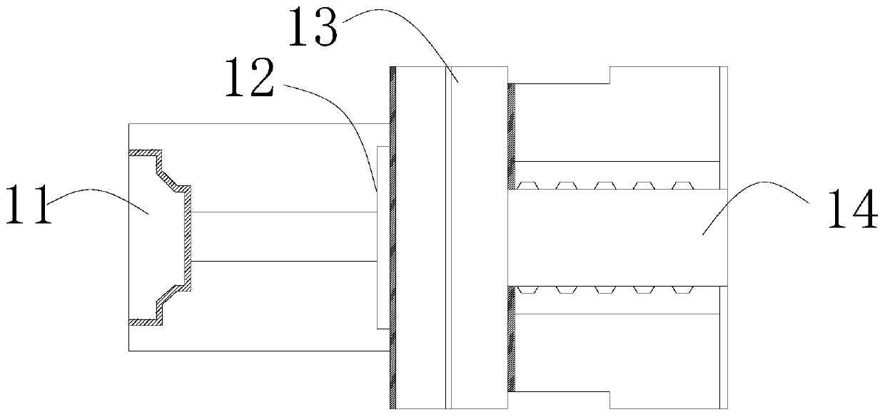
[0026] as attached figure 1 To attach Figure 5 Shown:

[0027] The invention provides a pneumatic impact wrench, the structure of which includes a clamp 1, a trigger 2, a handle 3, and a motor compartment 4, the clamp 1 is embedded and installed directly in front of the motor compartment 4, and the trigger 2 is movably engaged with the handle 3 on the left side, and fits with its inner end surface, the handle 3 is inlaid and installed directly under the motor compartment 4; the clamp 1 includes a clamping port 11, a buffer device 12, an overload protection mechanism 13, and a transmission shaft 14 , the clamping port 11 is inlaid and mounted on the left end of the buffer device 12, and the right end surface of the buffer device 12 is attached to the overload protection mechanism 13, and the overload protection mechanism 13 is located on the right side of the clamping port 11 Square, and connected to the transmission shaft 14 by welding, the transmission shaft 14 is located ...

Embodiment 2

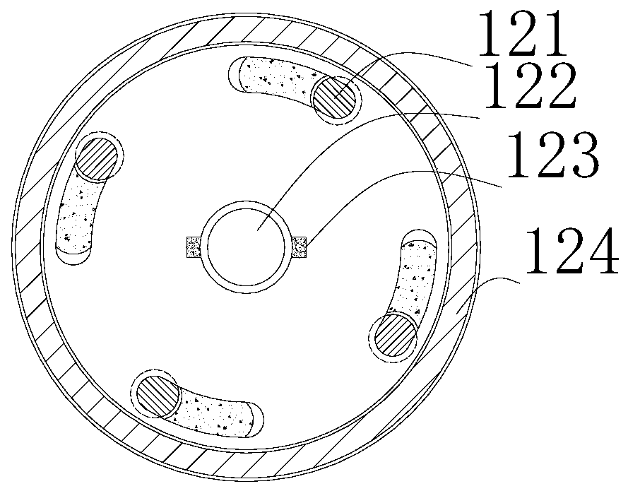
[0034] as attached Image 6 To attach Figure 8As shown: the overload protection mechanism 13 includes a fixed block 131, a second inlay groove 132, a spring 133, a fixed tooth 134, a connecting block 135, and a connecting plate 136, and the fixing block 131 is fixedly mounted on the upper and lower sides of the connecting plate 136 At both ends, the second mosaic groove 132 is located on the left side of the connecting plate 136 and connected to it, the spring 133 is located directly above the fixed tooth 134 and the left and right sides are welded to the fixed block 131, the The fixed teeth 134 are evenly distributed on the inner end surface of the connecting plate 136, the connecting block 135 is embedded and installed on the right side of the connecting plate 136, and the connecting plate 136 is located at the left and right ends of the fixed tooth 134, the fixed block 131 and There are four sets of springs 133, and they are evenly installed on the outside of the connecti...


PUM


Abstract

The invention discloses a pneumatic impact wrench. The pneumatic impact wrench structurally includes a clamp, a trigger, a grip and a motor compartment. The clamp is embedded and installed directly infront of the motor compartment. The trigger is movably clamped on the left side of the grip and attached to the inner end surface of the grip. The grip is inlaid and installed directly under the motor compartment. When a welded threaded nail or rivet occurs, the torsion force of a drive shaft and the blocking force of the rivet are gathered at inlay mechanisms, and the squeezing push of connecting buttons is used for forming buffer with flexibility and elasticity of rubber blocks, so that the overall rotation speed is rapidly reduced, and the problem of damage to the connection end surfaces of equipment parts caused by the wrong processing of the welded threaded nail and rivet can be effectively avoided.

Description

technical field [0001] The invention belongs to the field of auto parts, and more specifically relates to a pneumatic impact wrench. Background technique [0002] Pneumatic impact wrench is a kind of equipment commonly used in automobile processing and maintenance. It is usually composed of a motor, a rotating device, and a fixture. After being clamped by the fixture and the threaded screw, the rotating device is used to rotate the threaded screw. [0003] Based on the discovery of the above inventors, the existing methods mainly have the following deficiencies, such as: because rivets and screw screws are used for clamping and fixing in automobile processing, and the outer contours of the tops of the two are all hexagonal contours, which are difficult to distinguish, resulting in When using an impact wrench for rotary processing, it is easy to mistake the rivet for a threaded nail, and the weldability of the rivet can easily overload the rotating equipment of the impact wre...

Claims


Application Information

Patent Timeline
Patent Type & Authority Applications(China)
IPC IPC(8): B25B21/00B25B23/00B25B23/147B25B23/155
CPCB25B21/00B25B23/00B25B23/141B25B23/147B25B23/1475
Inventor 邹鑫
Owner 郑玲佳
Why Eureka
Try Eureka