Eureka AIR delivers breakthrough ideas for toughest innovation challenges, trusted by R&D personnel around the world.

Welding device

A welding device and welding head technology, used in tin feeding devices, auxiliary devices, welding equipment, etc., can solve problems such as poor safety, inaccurate welding, and burnt items, and achieve convenient welding, beautiful solder joints, and safe use. Effect

Pending Publication Date: 2020-08-28
ZHUHAI GREE PRECISION MOLD CO LTD +1
View PDF1 Cites 4 Cited by
  • Summary
  • Abstract
  • Description
  • Claims
  • Application Information

AI Technical Summary

Problems solved by technology

The electric soldering iron for traditional soldering needs to rely on human experience to control the flow of solder joints, and the welding is not accurate; the welding torch and the welding wire are separated in the traditional welding process, which requires two hands to complete, which is inconvenient; there is residual heat in the traditional soldering process, which is easy to burn and scald items , poor security
In order to solve such problems, the Chinese patent document CN201620488808.3 has disclosed an internal wire feeding device, but it has not substantially solved related problems

Method used


Image

  • Welding device
  • Welding device
  • Welding device

Examples


Embodiment Construction

[0026] Example embodiments will now be described more fully with reference to the accompanying drawings. Example embodiments may, however, be embodied in many forms and should not be construed as limited to the embodiments set forth herein; rather, these embodiments are provided so that this disclosure will be thorough and complete, and will fully convey the concept of example embodiments to those skilled in the art. The same reference numerals denote the same or similar parts in the drawings, and thus their repeated descriptions will be omitted.

[0027] Furthermore, the described features, structures, or characteristics may be combined in any suitable manner in one or more embodiments. In the following description, numerous specific details are provided in order to give a thorough understanding of embodiments of the present disclosure. However, those skilled in the art will appreciate that the technical solutions of the present disclosure may be practiced without one or mo...


PUM


Abstract

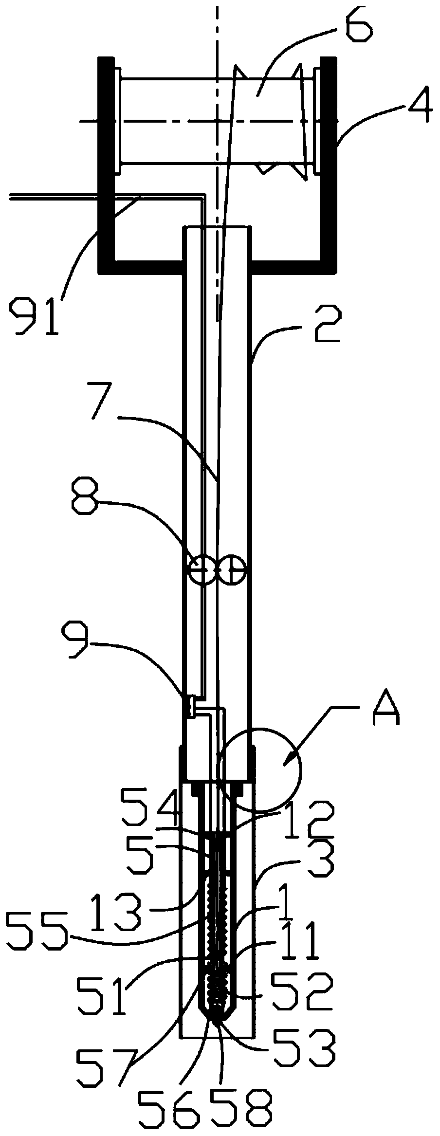
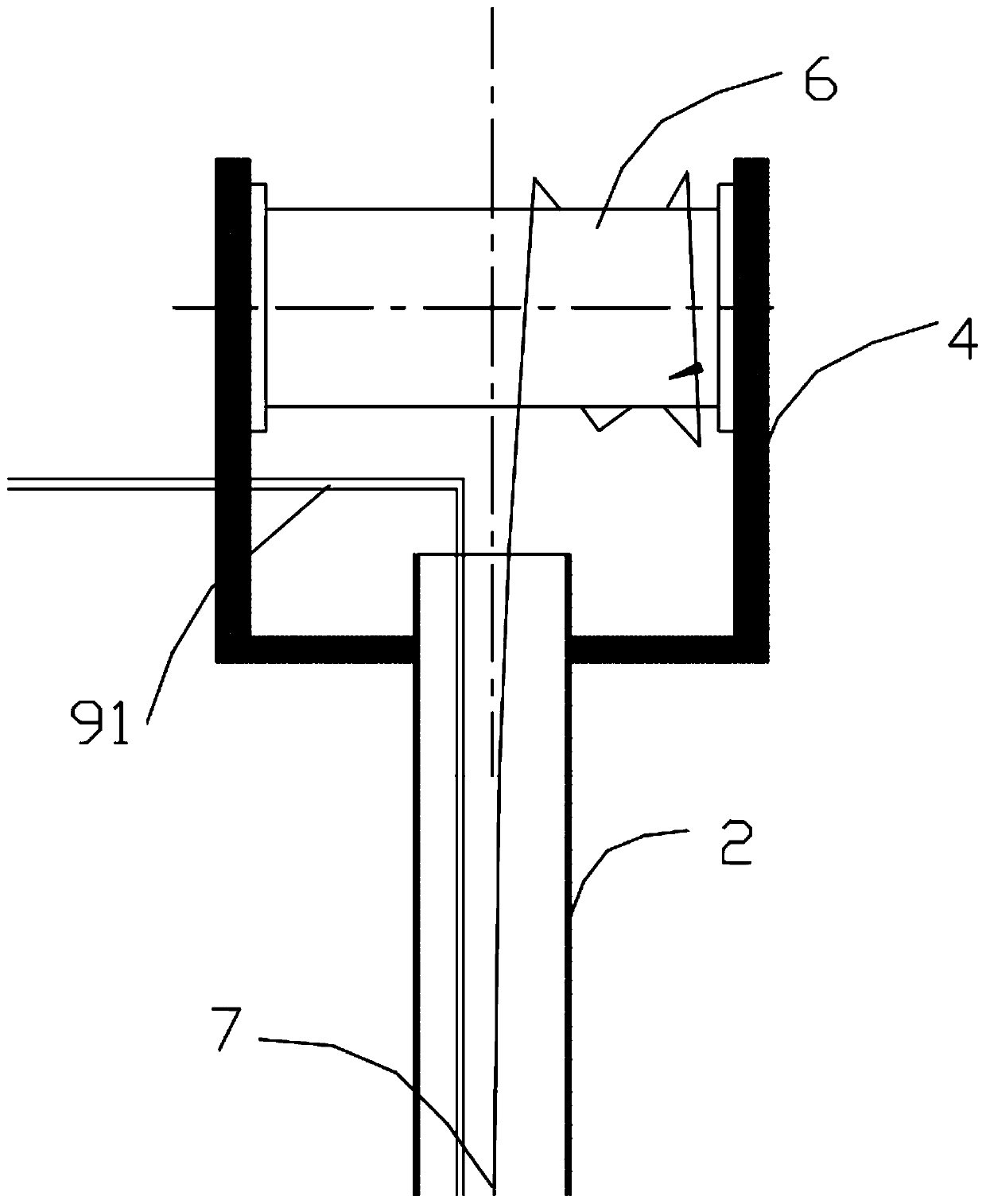
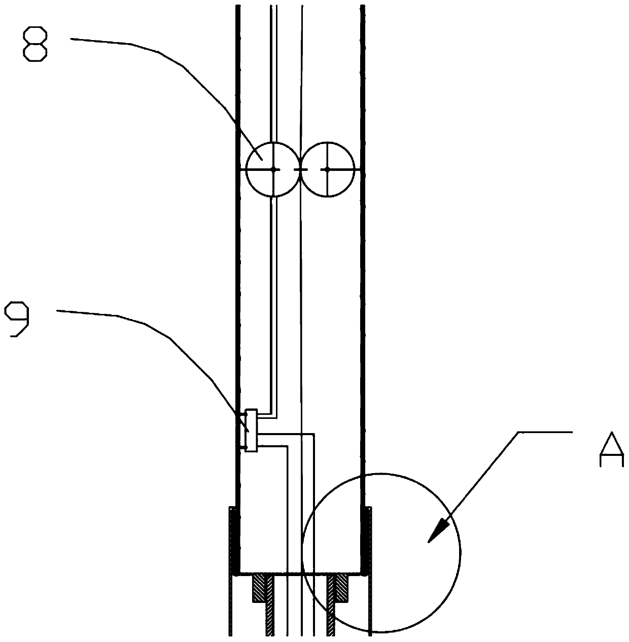
The invention relates to a welding device. A hollow portion is arranged in the welding device, a welding wire is conveyed through the hollow portion, a heating portion is arranged to heat and melt thewelding wire, the melted welding wire flows into a welding storage cavity through a welding draining groove, a welding head is pressed, so that a gap is formed between the welding head and an opening, and welding flux flows out. The welding device is convenient to operate, and welding work can be finished through single-hand control. The size of a welding point can be conveniently controlled, thewelding success rate is improved, and the welding attractiveness is improved. According to the scheme with a heat insulation shell, when the welding device is temporarily placed in the welding process, the welding head cannot scald objects, people and the like. Compared with a traditional welding device, the welding device is more convenient for welding; the flow of the welding point can be controlled according to the pressure, and the welding point is more attractive; and a telescopic protection sleeve is used for temporarily accommodating an electric soldering iron, and thus, the welding device is safer to use.

Description

technical field [0001] The invention relates to the field of welding, in particular to a welding device. Background technique [0002] With the development of electronic technology, integrated circuits have replaced traditional soldered circuit boards. But manual soldering is still indispensable in the electronics industry. Traditional manual soldering needs to hold the welding wire in one hand and the welding torch in the other hand, hold the electronic components, wait for the heating device to be energized and heated, and transfer the heat to the tip of the electric soldering iron through the vacuum sleeve. When the temperature is higher than the temperature of the welding wire (metal tin) , the welding wire is melted and dropped on the electronic components, and the circuit board can be cooled and solidified to complete the welding. The electric soldering iron for traditional soldering needs to rely on human experience to control the flow of solder joints, and the weld...

Claims


Application Information

Patent Timeline
Patent Type & Authority Applications(China)
IPC IPC(8): B23K3/06B23K3/08B23K3/00
CPCB23K3/00B23K3/06B23K3/0607B23K3/08
Inventor 支雄辉陈瑞珠蔡国旗徐欣杨郭雨薇杨丹丹刘芳博
Owner ZHUHAI GREE PRECISION MOLD CO LTD
Why Eureka
Eureka Blog
Learn More