A kind of construction material recovery equipment
A technology for recycling equipment and building materials, used in solid separation, chemical instruments and methods, grain processing, etc., and can solve problems such as single function
- Summary
- Abstract
- Description
- Claims
- Application Information
AI Technical Summary
Problems solved by technology
Method used
Image
Examples
specific Embodiment approach 1
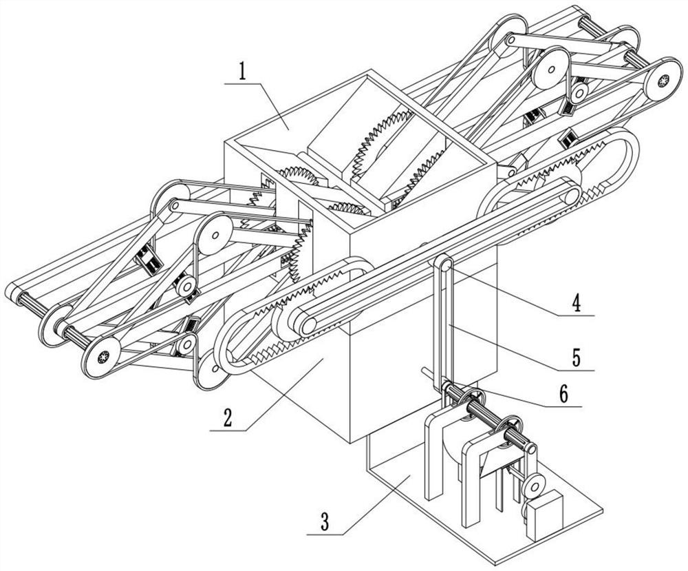
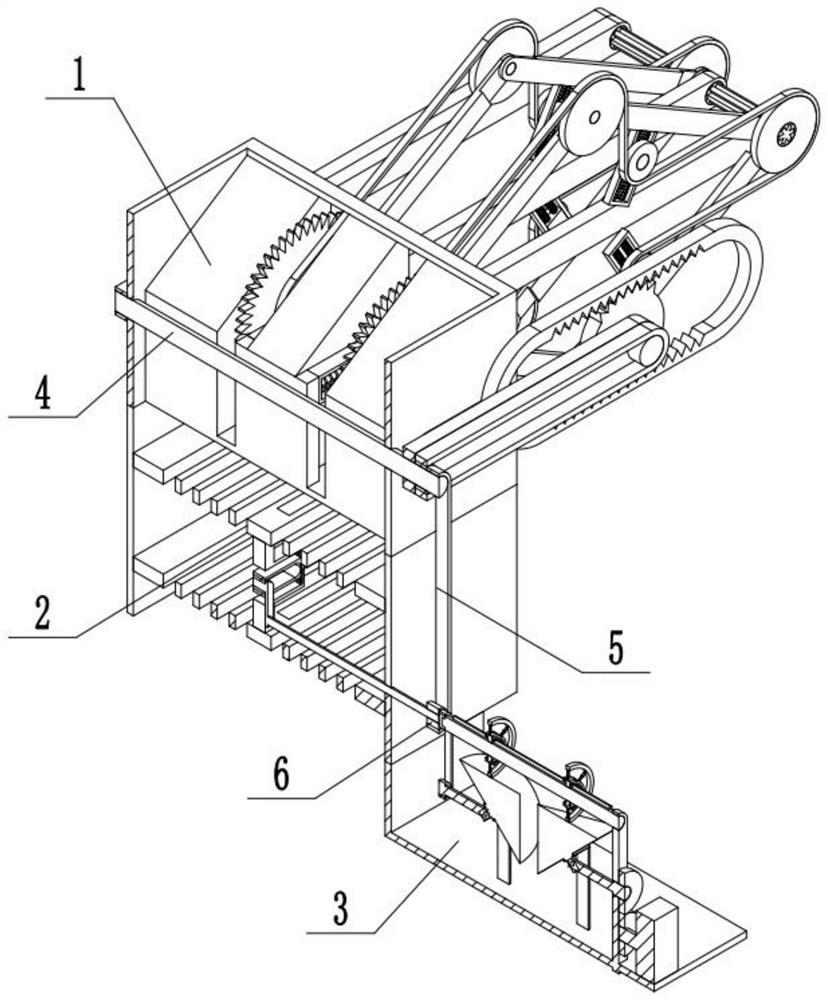
[0029]Bonded belowFigure 1-13In the present embodiment, a building material recovery apparatus includes a cutting assembly 1, a screening assembly 2, a power source assembly 3, a drive shaft 4, a drive shaft belt 5, and a fixed pulley 6, characterized in that the drive is driven The shaft belt 5 is connected to the drive shaft 4, the fixed pulley 6 is connected, the cutting assembly 1 is connected to the screen assembly 2, and the power source assembly 3 is connected to the sieving composition 2, and the cutting assembly 1 is connected to the drive shaft 4 The fixed pulley 6 is connected to the sieving assembly 2, the power source assembly 3.
specific Embodiment approach 2
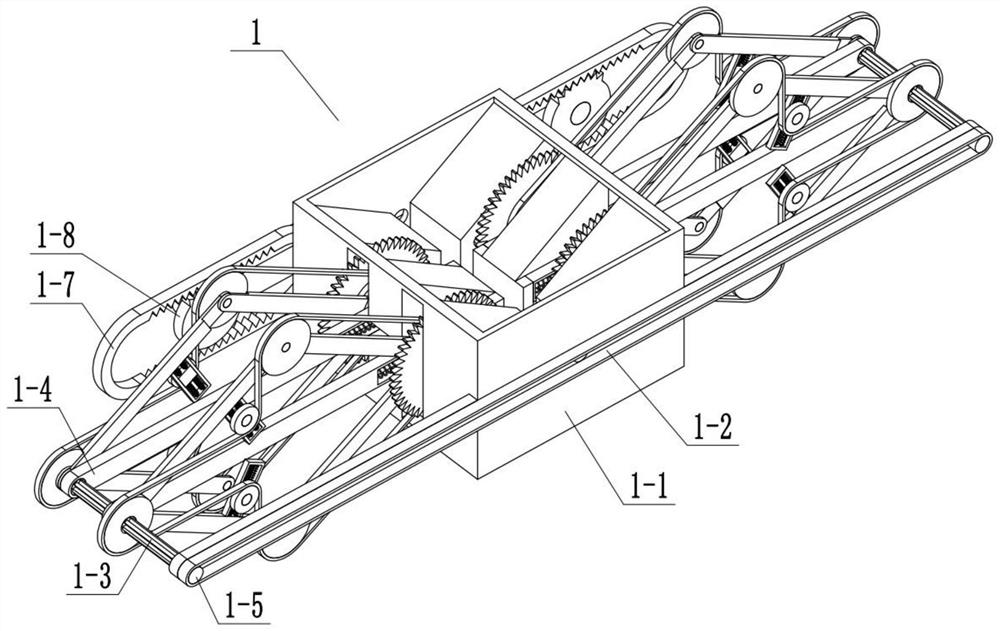
[0031]Bonded belowFigure 1-13In the present embodiment, the present embodiment will further explain the embodiment, and the cutting assembly 1 includes a cutting bottom plate 1-1, a transmission belt 1-2, a prismatic rotor 1-3, a tool holder 1-4, a transmission belt Wheel 1-5, transmission belt 2 1-6, crossbar 1-7, half gear one-8, mid-end connecting rod 1-9, mid-end connecting rod 2-10, hinge rod 1-11 , Transmission belt 1-13, cutting saw 1-13, transmission belt three 1-14, transmission belt three 1-15, medium slide one 1-16, transmission belt three 1-17, medium slide rod 1 1 -18, Mid-end sliding rod spring one 1-19, transmission belt 1-20, mid-end rectangular slider 1-21, medium slide rod 2 1-22, medium-end slider spring 2 1-23, The hinge 2 1-24, the drive belt 1-2 is connected between the two transmission pulleys 1-5, the drive pulley 1-5 is fixed to the prismatic turn rod 1-3, and the drive belt 1-5 and Cutting bottom plate 1-1 rotates, half gear 1-8 rotates to the cutting botto...
specific Embodiment approach 3
[0033]Bonded belowFigure 1-13In the present embodiment, the present embodiment will further explain the embodiment, and the screening assembly 2 includes a screen frame 2-1, an eccentric rod 2-2, a rectangular screen plate, 2-3, rectangular screen hole one 2 -4, inner spring 2-5, internal tester 2-6, rectangular screen 2-7, rectangular screen 2-8, connecting rod 2-9, curved rod one 2-10, arc Bar 2 2-11, Inner Spring 2 2-12, Inner Rod 2-13, Inner End Car Rod 2-14, Inner Delivery Card Trough One 2-15, Eccentric Rod 2-2 and Sieve Divided frame 2-1 rotates the connection, the internal tester 2-6 and the screen frame 2-1 fixed connection, rectangular screen 2-3, rectangular screen 2 2-7 and internal test slip post 2-6 Slide connection, rectangular screen one 2-4, rectangular screen 2-8 is disposed on the rectangular screen 2-3, rectangular screen 2-7, inner spring 2-5, inner spring 2 2-12 is connected to the internal test 2-6, the connecting rod 2-9 is fixed to the rectangular screen 2-3...
PUM
 Abstract
Description
Claims
Application Information
 - R&D Engineer
- R&D Manager
- IP Professional
- Industry Leading Data Capabilities
- Powerful AI technology
- Patent DNA Extraction
Browse by: Latest US Patents, China's latest patents, Technical Efficacy Thesaurus, Application Domain, Technology Topic, Popular Technical Reports.
© 2024 PatSnap. All rights reserved.Legal|Privacy policy|Modern Slavery Act Transparency Statement|Sitemap|About US| Contact US: help@patsnap.com


