Skin surface ointment auxiliary applicator for dermatological department
A dermatology and applicator technology, applied in the direction of drug devices, etc., can solve the problems of troublesome operation, easy to cause cross infection, etc., to achieve the effect of convenient operation and avoid cross infection
- Summary
- Abstract
- Description
- Claims
- Application Information
AI Technical Summary
Problems solved by technology
Method used
Image
Examples
Embodiment 1
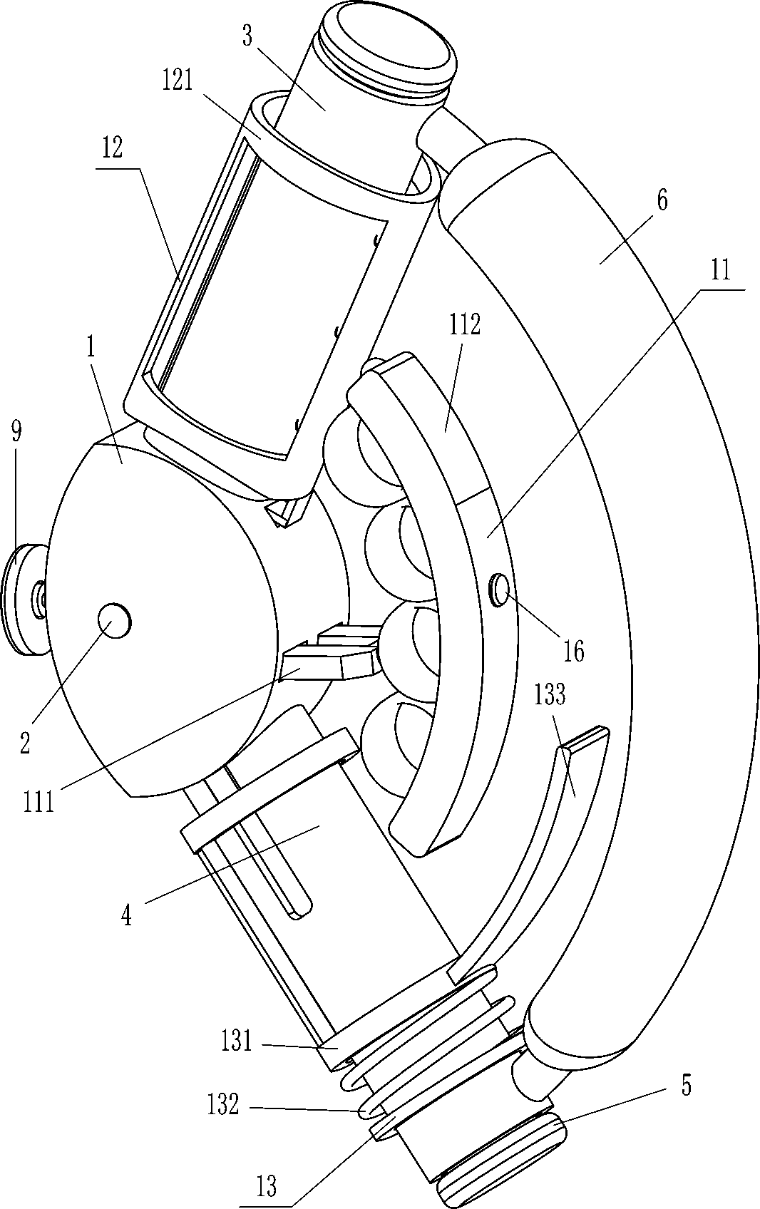
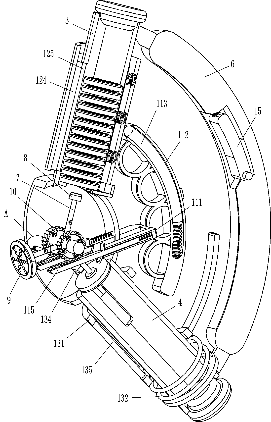
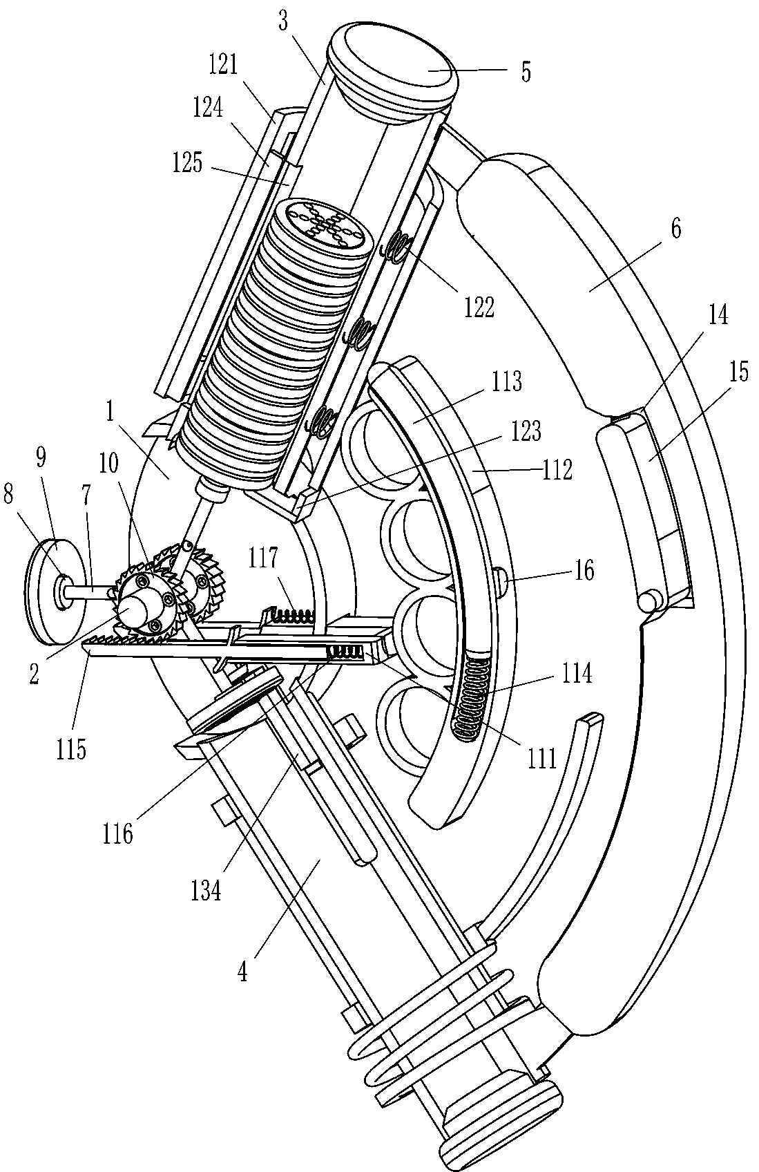
[0022] refer to Figure 1-Figure 3 , an auxiliary skin ointment applicator for dermatology, comprising a frame body 1, a rotating shaft 2, a material storage hollow cylinder 3, a collection hollow cylinder 4, a rubber stopper 5, an arc handle 6, a fixed rod 7, and a circular magnet 8 , a ratchet 10, a driving mechanism 11 and a blocking mechanism 12. The left side of the frame body 1 is open, and the middle part of the left side of the frame body 1 is rotatably connected with a rotating shaft 2, and the middle part of the rotating shaft 2 is uniformly spaced fixed There are three fixed rods 7 connected, the outer ends of the fixed rods 7 are fixedly connected with a circular magnet 8, the front and rear parts of the rotating shaft 2 are fixedly connected with a ratchet 10, the right part of the frame body 1 is provided with a driving mechanism 11, and the driving mechanism 11 is in contact with the ratchet 10 Cooperate, the top of the frame body 1 is fixedly connected with the...
Embodiment 2
[0029] refer to Figure 1-Figure 3 Compared with Embodiment 1, the main difference of this embodiment is that in this embodiment, a pushing mechanism 13 is also included, and the pushing mechanism 13 includes a collar 131, a fourth spring 132, an arc contact plate 133, an L-shaped push Plate 134 and connecting rod 135, two collars 131 are sleeved slidingly on the outer side of collecting hollow tube 4, and there are four connecting rods evenly spaced between the bottom left side of the upper collar 131 and the top left side of the lower collar 131. Rod 135, a fourth spring 132 is wound between the bottom of the lower collar 131 and the lower part of the outer side of the collection hollow cylinder 4, and the right side of the outer side of the lower collar 131 is fixedly connected with an arc-shaped contact plate 133 that matches the arc-shaped pull rod 112. The upper part of the collection hollow cylinder 4 is slidingly provided with an L-shaped push plate 134 in the middle o...
Embodiment 3
[0032] refer to Figure 2-Figure 4 Compared with Embodiment 1 and Embodiment 2, the main difference of this embodiment is that in this embodiment, a magnetic rod 15 and a magnet block 16 are also included. There is a groove 14 in the middle of the inner surface of the arc-shaped handle 6. Between the lower parts of both sides, the magnetic bar 15 that can fix the arc pull bar 112 is hinged.
[0033] Also include sleeve 17, clamping rod 18 and the fifth spring 19, sleeve 17 is fixedly connected to the upper left side of the front and rear sides of the frame body 1, and sleeve 17 is slidingly provided with clamping rod 18, clamping rod 18 The fifth spring 19 is connected between the outer end and the inner surface of the sleeve 17, and the middle part of the front and rear sides of the fixed rod 7 has a draw-in groove 20, and the inner end of the draw-in rod 18 is located in the draw-in groove 20 to cooperate with it.
[0034] When the device does not need to be used, pull the ...
PUM
 Abstract
Description
Claims
Application Information
 - Generate Ideas
- Intellectual Property
- Life Sciences
- Materials
- Tech Scout
- Unparalleled Data Quality
- Higher Quality Content
- 60% Fewer Hallucinations
Browse by: Latest US Patents, China's latest patents, Technical Efficacy Thesaurus, Application Domain, Technology Topic, Popular Technical Reports.
© 2025 PatSnap. All rights reserved.Legal|Privacy policy|Modern Slavery Act Transparency Statement|Sitemap|About US| Contact US: help@patsnap.com


