Method for deriving proper cutting condition of polarization plate

A technology for polarizers and conditions, applied in the directions of polarizers, optical elements, optical elements, etc., can solve the problems of reduced durability, inability to set the correct position of the polarizer 100, deterioration of bulk modulus adhesion, etc., to minimize leakage Effect

Active Publication Date: 2020-08-25
SHANJIN OPTOELECTRONICS SUZHOU CO LTD
View PDF10 Cites 2 Cited by
  • Summary
  • Abstract
  • Description
  • Claims
  • Application Information

AI Technical Summary

Problems solved by technology

However, since it is difficult to change the position of the transportation facility 1 once the transportation facility 1 is fixedly installed, leakage of only a small amount of the adhesive 151 on the transportation facility 1 also results in that the polarizing plate 100 cannot be set in the intended position for the attaching process or cleaning. the exact position of the process, resulting in a defect in the product
[0006] In the related art, a hard adhesive made by changing the composition ratio of segments contained in the adhesive is sometimes used to improve the adhesive The degree of leakage, but in this case, a problem of deterioration of adhesion caused by an increase in bulk modulus or a problem of reduced durability arises

Method used


Image

  • Method for deriving proper cutting condition of polarization plate
  • Method for deriving proper cutting condition of polarization plate
  • Method for deriving proper cutting condition of polarization plate

Examples


Embodiment Construction

[0030] Hereinafter, the present invention will be described in detail with reference to the accompanying drawings.

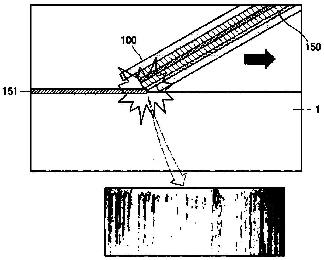
[0031] image 3 is a flowchart illustrating a method of obtaining conditions for properly cutting a polarizing plate according to the present invention, Figure 4 is a diagram showing an experimental device according to the present invention, which was made by simulating the movement of a polarizing plate to obtain conditions for properly cutting the polarizing plate.

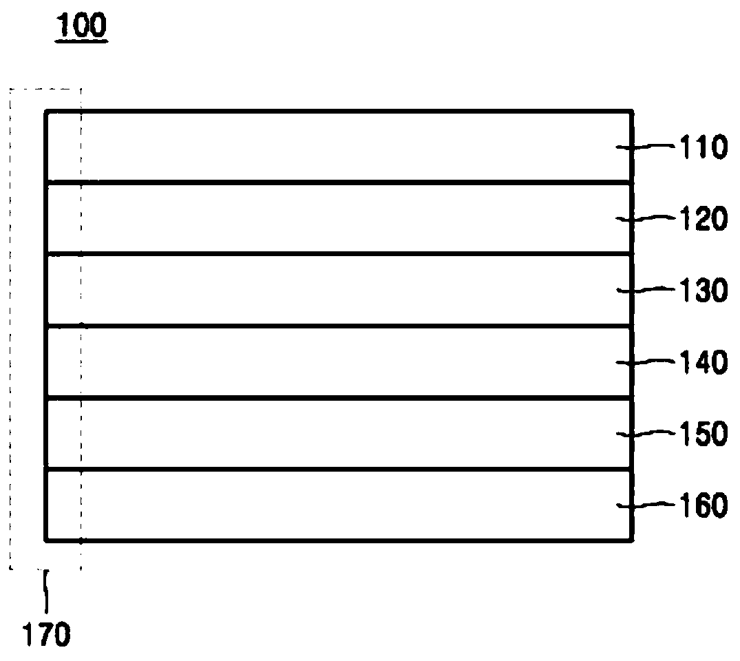
[0032] The present invention relates to a method of obtaining conditions for properly cutting a polarizing plate based on a measurement standard regarding leakage of an adhesive 151 which is previously set with respect to a frictional force applied between a polarizing plate 100 and a guide unit 200 information about the data. refer to image 3 , the method may include (a) preparing the polarizing plate 100 including the adhesive layer 150 and having the cut surface 170 formed by cutting based...


PUM


Abstract

A method for deriving a proper cutting condition of a polarization plate according to an embodiment of the present invention may comprise the steps of: (a) preparing a polarization plate including anadhesive layer and having a cut surface which is cut and formed thereon according to a predetermined cutting condition; (b) providing the polarization plate to a guide part such that one end of the polarization plate comes into contact with the guide part; (c) moving the polarization plate on the guide part; (d) measuring frictional force applied between the polarization plate and the guide part while the polarization plate is moved; and (e) deriving a proper cutting condition of the polarization plate on the basis of a value of the measured frictional force and a reference for determination on whether the adhesive of the polarization plate leaks, wherein the reference has been informationalized in advance by using frictional force data.

Description

technical field [0001] The present invention relates to a method of obtaining conditions for properly cutting polarizing plates, and more particularly, to a method of obtaining conditions for properly cutting polarizing plates based on adhesive leakage measurement standards. Background technique [0002] The polarizing plate is configured to realize a desired image by polarizing light vibrating in all directions so that the light vibrates only in a specific direction. Polarizing plates are attached to both sides of the liquid crystal display (LCD) panel. [0003] Such as figure 1 As shown, the polarizing plate 100 has a layered structure including: a polarizer layer 130 made of PVA material, an upper support layer 120 attached to both surfaces of the polarizer layer 130, and a lower support layer. layer 140, a protective film layer 110 formed on the upper portion of the upper support layer 120 and configured to protect the polarizer layer 130 from external environments suc...

Claims


Application Information

Patent Timeline
Patent Type & Authority Applications(China)
IPC IPC(8): G02B5/30
CPCG02B5/30B29D11/00644B29D11/00951B29D11/00932G02B5/3033B26D1/00
Inventor 李文赞朴正岵李镇洙辛富建
Owner SHANJIN OPTOELECTRONICS SUZHOU CO LTD
Why Eureka
Try Eureka