
A capacitor array switching method for successive approximation analog-to-digital converter is provided

An analog-to-digital converter, successive approximation technology, applied in analog-to-digital conversion, code conversion, instruments, etc., can solve the problems of large change in common mode level, increase circuit cost, consumption, etc., to save circuit area and Cost, Capacitor Saving Effect

Pending Publication Date: 2020-08-25
UNIV OF ELECTRONIC SCI & TECH OF CHINA
View PDF2 Cites 2 Cited by
  • Summary
  • Abstract
  • Description
  • Claims
  • Application Information

AI Technical Summary

Problems solved by technology

The capacitor array SAR ADC implements the successive approximation algorithm based on the principle of charge redistribution. The capacitor array used will multiply as the number of bits of the ADC increases. For ADCs with high conversion accuracy, the capacitor array will consume a lot of layout area, increasing circuit cost
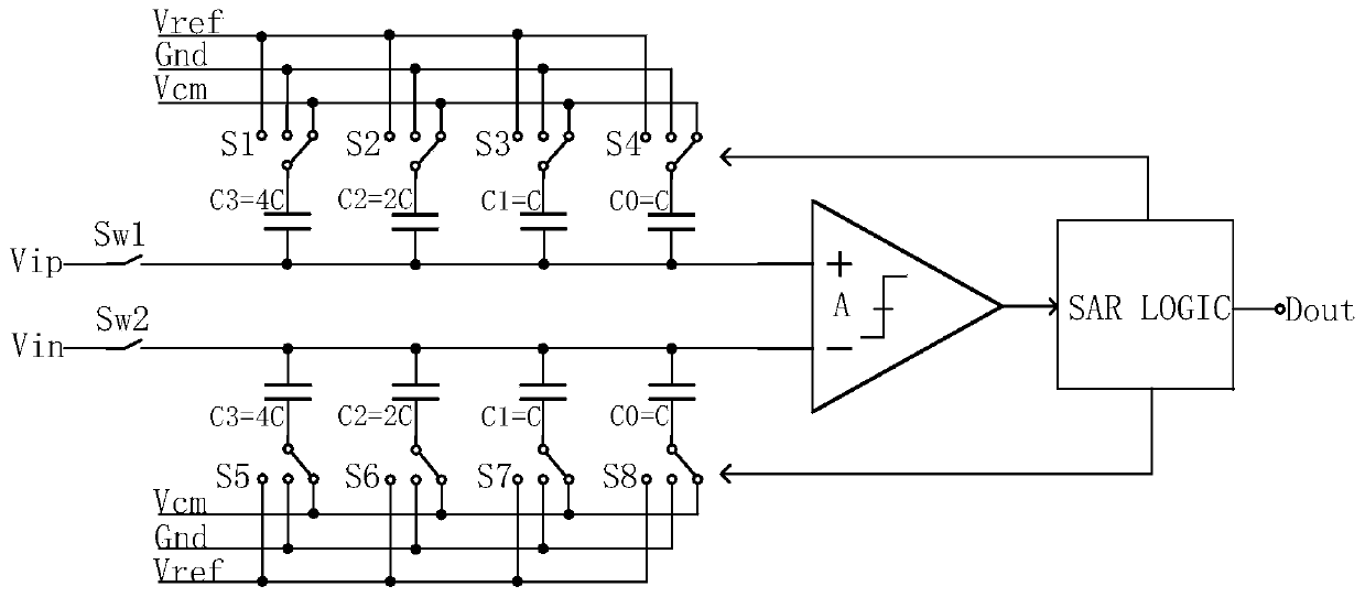
[0003] Among the currently commonly used switching schemes, the monotonic structure switching scheme needs to achieve N-bit conversion accuracy, and the capacitor array needs 2 N A unit capacitance, and during the conversion process, the common-mode level will change greatly, and the design requirements for the comparator are relatively high; the common-mode level V CM Although the -based switching scheme keeps the common-mode level of the comparator stable, it also consumes 2 N unit capacitance

Method used


Image

  • A capacitor array switching method for successive approximation analog-to-digital converter is provided
  • A capacitor array switching method for successive approximation analog-to-digital converter is provided
  • A capacitor array switching method for successive approximation analog-to-digital converter is provided

Examples


Embodiment Construction

[0032] The technical solution of the present invention will be described in detail below in conjunction with the accompanying drawings and specific embodiments.

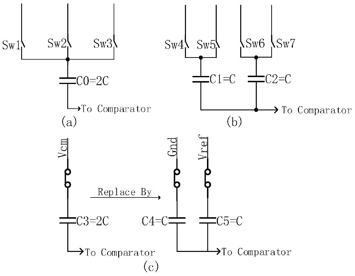
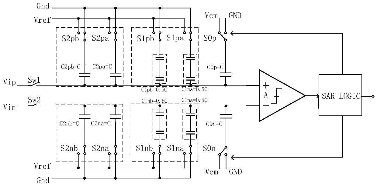
[0033] Such as figure 1 Shown is the common-mode level V CM -based switching scheme schematic, figure 2 is the schematic diagram of the split capacitor array switch scheme proposed by the present invention, it can be seen that compared to figure 1 Common mode level V CM -based switch scheme capacitor array, the present invention splits each weighted capacitor into two parallel split weighted capacitors whose capacitance value is 1 / 2 of the original capacitor value, figure 1 In the switching scheme shown, the weighted capacitor array includes 4 weighted potentials at the positive phase end and 4 weighted capacitors at the negative phase end. It takes 2 4 unit capacitance. The new switching method proposed by the present invention adds redundant capacitors into the calculation of charge redistribution, and uses a...


PUM


Abstract

The invention discloses a capacitor array switching method for a successive approximation type analog-to-digital converter, and belongs to the technical field of electronic circuits. A weighting capacitor array in the successive approximation type analog-to-digital converter comprises a one-bit positive phase end redundant capacitor, a one-bit negative phase end redundant capacitor, an N-2-bit positive phase end weighting capacitor and an N-2-bit negative phase end weighting capacitor. According to the invention, each bit of weighting capacitor is split into two split weighting capacitors which are connected in parallel and have equal capacitance values; a redundant capacitor is added into charge redistribution operation, and a monotonous switching mode is used on the redundant capacitor,so that only 2N-1 unit capacitors are needed for realizing N-bit conversion precision, and compared with a common-mode level VCM-based switching scheme, half of the capacitor is saved, and the circuitarea and the cost are saved; meanwhile, the characteristic that the common-mode level of the comparator is not changed in a common-mode level VCM-based switching scheme is basically reserved, the common-mode level is changed only in the last comparison, and the problem that the design requirement for the comparator is high due to the fact that the common-mode level is greatly changed is solved.

Description

technical field [0001] The invention belongs to the technical field of electronic circuits, and in particular relates to a capacitor array switching method for a successive approximation analog-to-digital converter. Background technique [0002] An analog-to-digital converter (ADC) is one of the core modules of various electronic terminal equipment, which realizes the conversion of analog signals to digital signals. Among various analog-to-digital converters, the successive approximation analog-to-digital converter (SAR ADC) is very suitable for low-power applications because of its simple structure and few analog modules. The capacitor array SAR ADC implements the successive approximation algorithm based on the principle of charge redistribution. The capacitor array used will multiply as the number of bits of the ADC increases. For ADCs with high conversion accuracy, the capacitor array will consume a lot of The layout area increases the circuit cost. [0003] Among the c...

Claims


Application Information

Patent Timeline
IPC IPC(8): H03M1/38
CPCH03M1/38
Inventor 李泽宏杨耀杰王其鹤胡任任蔡景宜
Owner UNIV OF ELECTRONIC SCI & TECH OF CHINA
Learn More