
Rotating mirror unit for laser radar, corresponding laser radar and using method

A technology of laser radar and rotating mirror, applied in the field of radar, can solve the problems of reducing volume, large volume, poor scanning quality of laser radar, etc., to achieve the effect of reducing volume and solving large volume

Pending Publication Date: 2020-08-25
HESAI TECH CO LTD
View PDF0 Cites 6 Cited by
  • Summary
  • Abstract
  • Description
  • Claims
  • Application Information

AI Technical Summary

Problems solved by technology

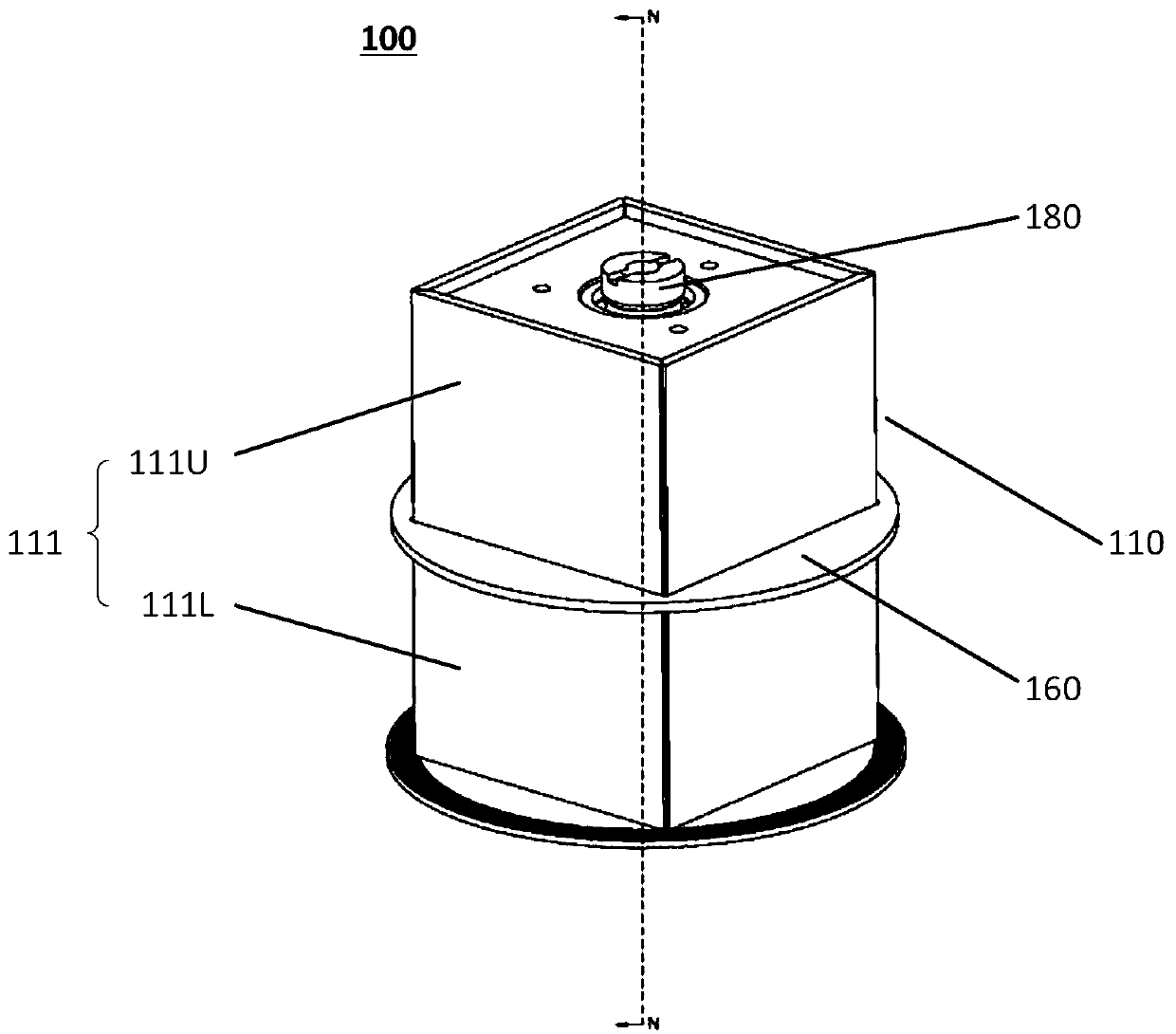
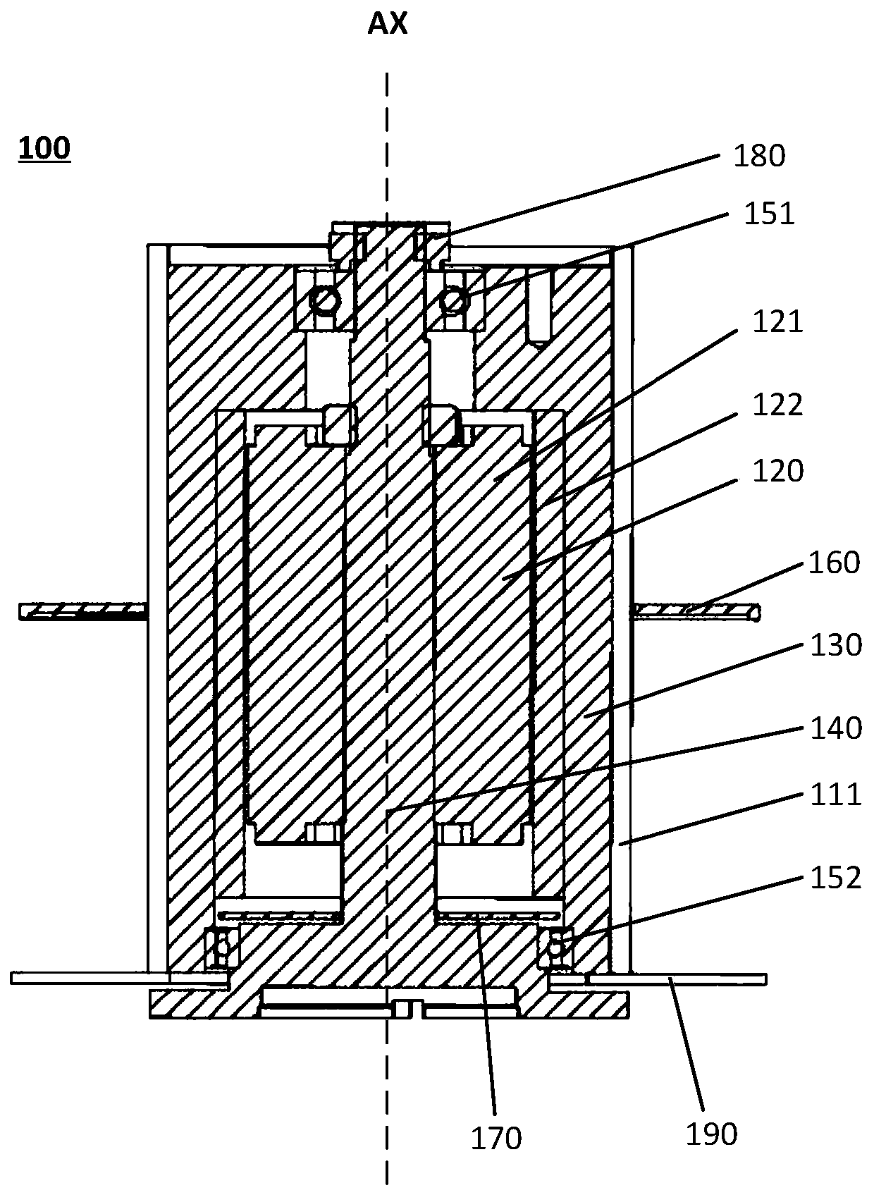
[0006] The rotating mirror laser radar of the present invention reduces its volume by building the motor in the polygonal space surrounded by the multi-faceted rotating mirror, and encrypts the scanning line by setting a corresponding angle for the multi-faceted rotating mirror, which solves the problem of laser radar in the prior art. Problems such as the large size of the radar due to its high altitude and the poor quality of lidar scans

Method used


Image

  • Rotating mirror unit for laser radar, corresponding laser radar and using method
  • Rotating mirror unit for laser radar, corresponding laser radar and using method
  • Rotating mirror unit for laser radar, corresponding laser radar and using method

Examples


Embodiment Construction

[0047] In the following, only some exemplary embodiments are briefly described. As those skilled in the art would realize, the described embodiments may be modified in various different ways, all without departing from the spirit or scope of the present invention. Accordingly, the drawings and descriptions are to be regarded as illustrative in nature and not restrictive.

[0048]In describing the present invention, it is to be understood that the terms "center", "longitudinal", "transverse", "length", "width", "thickness", "upper", "lower", "front", " Back", "Left", "Right", "Vertical", "Horizontal", "Top", "Bottom", "Inner", "Outer", "Clockwise", "Counterclockwise", etc. or The positional relationship is based on the orientation or positional relationship shown in the drawings, which is only for the convenience of describing the present invention and simplifying the description, rather than indicating or implying that the referred device or element must have a specific orien...


PUM


Abstract

The invention discloses a rotating mirror unit suitable for a laser radar. The rotating mirror unit comprises a polyhedral rotating mirror part which is provided with an even number of reflecting surfaces forming a polygon in an enclosing manner, and is used for changing an angle of a light beam incident on the reflecting surfaces, a motor configured to drive the polyhedral rotating mirror part torotate around the axis of the polyhedral rotating mirror part, wherein each reflective surface includes an upper portion and a lower portion separated by a light blocking region. The rotating mirrorunit is advantaged in that the height of the rotating mirror type laser radar is reduced, the size of the laser radar is reduced, and scanning precision and the scanning quality of the laser radar areimproved.

Description

technical field [0001] The present disclosure relates to the field of radar, and in particular to a rotating mirror unit for lidar, a corresponding lidar and a use method. Background technique [0002] Lidar is a radar system that detects characteristic quantities such as target position and speed by emitting laser beams. It is an advanced detection method that combines laser technology with photoelectric detection technology. Because of its high resolution, good concealment, strong anti-interference ability, good low-altitude detection performance, small size and light weight, Lidar is widely used in unmanned driving, drones, intelligent robots, transportation communications, Energy security testing, resource exploration and other fields. With the rapid development of autonomous driving technology in recent years, lidar has become indispensable as the core sensor for mid-range perception in the field of autonomous driving. [0003] In the field of autonomous driving, on-b...

Claims


Application Information

Patent Timeline
IPC IPC(8): G01S17/02G01S7/481
CPCG01S7/4812G01S7/4817G01S17/02
Inventor 韩筱敏顾亮曾昭明向少卿
Owner HESAI TECH CO LTD
Learn More