Elevator shaft construction device and construction method

A technology of construction device and elevator shaft, which is applied to hoisting devices, elevators in buildings, safety devices of hoisting equipment, etc., can solve the problems of slow elevator shaft construction, high risk, elevator car running jam or accident, etc. To achieve the effect of improving construction speed and construction quality, ensuring construction quality and reasonable construction steps

Active Publication Date: 2020-08-25
SINOPEC SSC +1
View PDF8 Cites 0 Cited by
  • Summary
  • Abstract
  • Description
  • Claims
  • Application Information

AI Technical Summary

Problems solved by technology

[0002] At present, buildings and buildings are being built higher and higher, and the construction of elevator shafts is becoming more and more difficult, especially in newly designed buildings. It is separated from the construction of the building and does not affect each other. Because the construction of the elevator shaft is too slow, it is difficult to ensure the concentricity of the ladder, resulting in frequent jams or accidents in the operation of the elevator car, and at the same time restricting the construction speed of the building
The construction methods used in the past are not suitable, such as scaffolding construction methods, electric crawling construction methods, as the construction difficulty increases, the danger becomes more and more dangerous, and it is difficult to guarantee the construction quality

Method used


Image

  • Elevator shaft construction device and construction method

Examples


Embodiment Construction

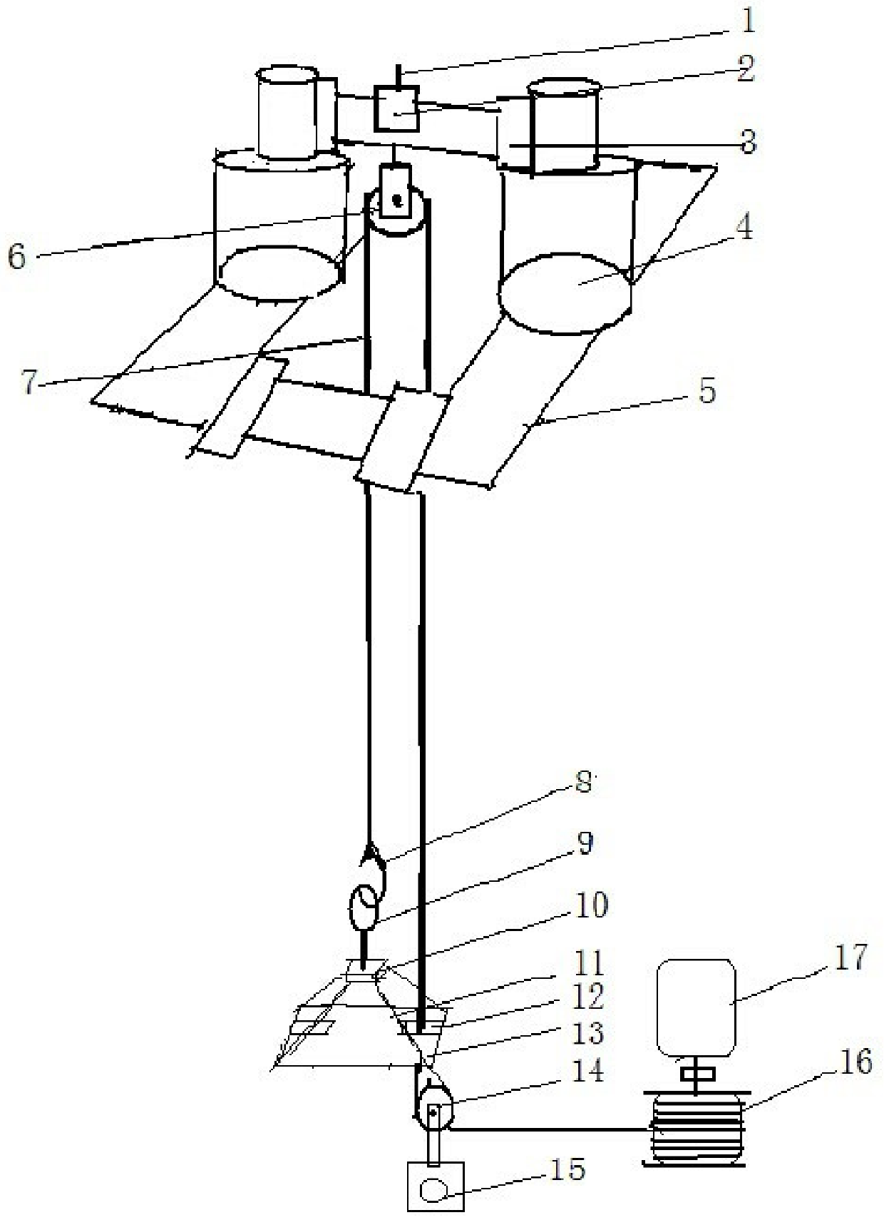
[0027] In order to further clarify the technical solution of the present invention, the following will be clearly and completely described through embodiments in conjunction with the accompanying drawings of the title book of the present invention. An elevator shaft construction device includes a driving mechanism, a suspension mechanism and a working platform, and the driving Mechanism includes self-control type speed-regulating motor 17, drum 16, wire rope 7, remote controller, and suspension mechanism includes piston type suspension frame 3, hydraulic cylinder 4, plug-in type hydraulic cylinder rectangular base 5 and suspension pulley 6. The end of the longitudinal side of the rectangular base of the hydraulic cylinder is provided with a sleeve inward and horizontally. The horizontal side is inserted into the sleeve and fixed by a pin. The hydraulic cylinder is symmetrically welded or fixed in the middle of the horizontal side. 1. The horizontal connecting sleeve welded on t...


PUM


Abstract

The invention relates to an elevator shaft construction device. The elevator shaft construction device comprises a driving mechanism, a suspension mechanism and an operation platform, the driving mechanism comprises a self-control speed regulating motor, a roller, a steel wire rope and a remote controller, the suspension mechanism comprises a piston type suspension frame, hydraulic cylinders, a plug-in type hydraulic cylinder rectangular base and a suspension pulley, insertion sleeves are arranged at the ends of the longitudinal edges of the plug-in type hydraulic cylinder rectangular base inwards in the transverse direction, the transverse edges are inserted into the insertion sleeves and fixed through bolt pins, the hydraulic cylinders are symmetrically welded or fixed to the middles ofthe transverse edges, the piston type suspension frame is composed of pistons, transverse connecting sleeves welded to the upper portions of the pistons and a cross beam inserted into the connecting sleeves, a pulley suspender, a fixed pressing cap and a ground pulley wound by a steel wire rope are vertically and downwards arranged in the middle of the cross beam, one end of the steel wire rope iswound and fixed on the roller, and the other end of the steel wire rope is connected with a lifting ring of the operation platform through the ground pulley, the suspension pulley and a self-lockinghook on the steel wire rope. According to the elevator shaft construction device, multi-person cooperative construction can be achieved on the operation platform, cooperation is tacit, and the construction quality can be guaranteed.

Description

technical field [0001] The invention belongs to the technical field of building elevator installation and construction, and in particular relates to an elevator shaft construction device and a construction method. Background technique [0002] At present, buildings and buildings are being built higher and higher, and the construction of elevator shafts is becoming more and more difficult, especially in newly designed buildings. It is separated from the construction of the building and does not affect each other. Because the construction of the elevator shaft is too slow, it is difficult to ensure the concentricity of the ladder, resulting in frequent jams or accidents in the operation of the elevator car, and at the same time restricting the construction speed of the building. The construction methods used in the past are not suitable, such as scaffolding construction methods and electric crawling construction methods. With the increase of construction difficulty, the danger...

Claims


Application Information

Patent Timeline
IPC IPC(8): B66F11/00B66F13/00B66F17/00B66B11/00E04F17/00E04G21/14
CPCB66B11/0005B66F11/00B66F13/00B66F17/006E04F17/005E04G21/14
Inventor 刘超白方民赵彦姜则才刘希民陈珏刘敏刘宗超刘森李学锴
Owner SINOPEC SSC
Why Eureka
Try Eureka