
Wood grooving machine tool

A technology for grooving and machine tools, applied in the field of machine tools, can solve problems such as being unenvironmental, affecting the health of workers, and not being able to collect wood chips.

Pending Publication Date: 2020-08-25
YANCHENG INST OF IND TECH
View PDF0 Cites 2 Cited by
  • Summary
  • Abstract
  • Description
  • Claims
  • Application Information

AI Technical Summary

Problems solved by technology

[0004] The purpose of the present invention is to solve the disadvantages in the prior art that the wood grooving machine tool cannot collect the sawdust produced by grooving, resulting in the mixing of sawdust in the air in the grooving area, which affects the health of the staff and is not environmentally friendly. Proposed Wood Grooving Machine Tool

Method used


Image

  • Wood grooving machine tool
  • Wood grooving machine tool
  • Wood grooving machine tool

Examples


Embodiment 1

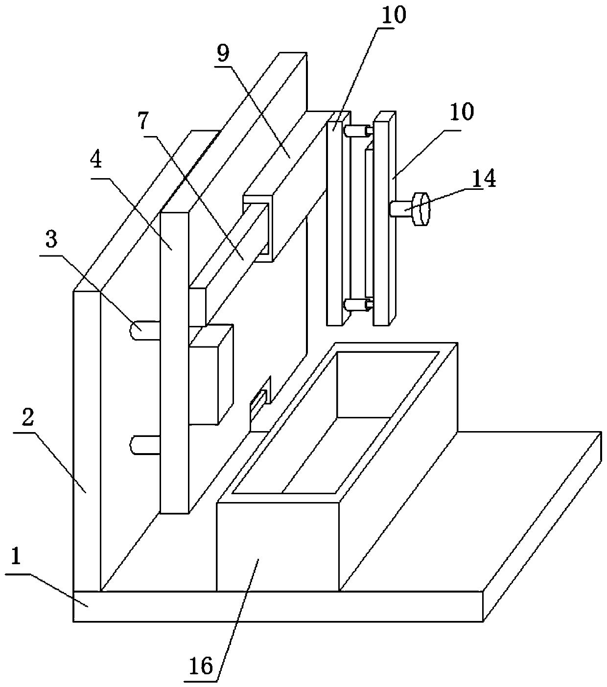
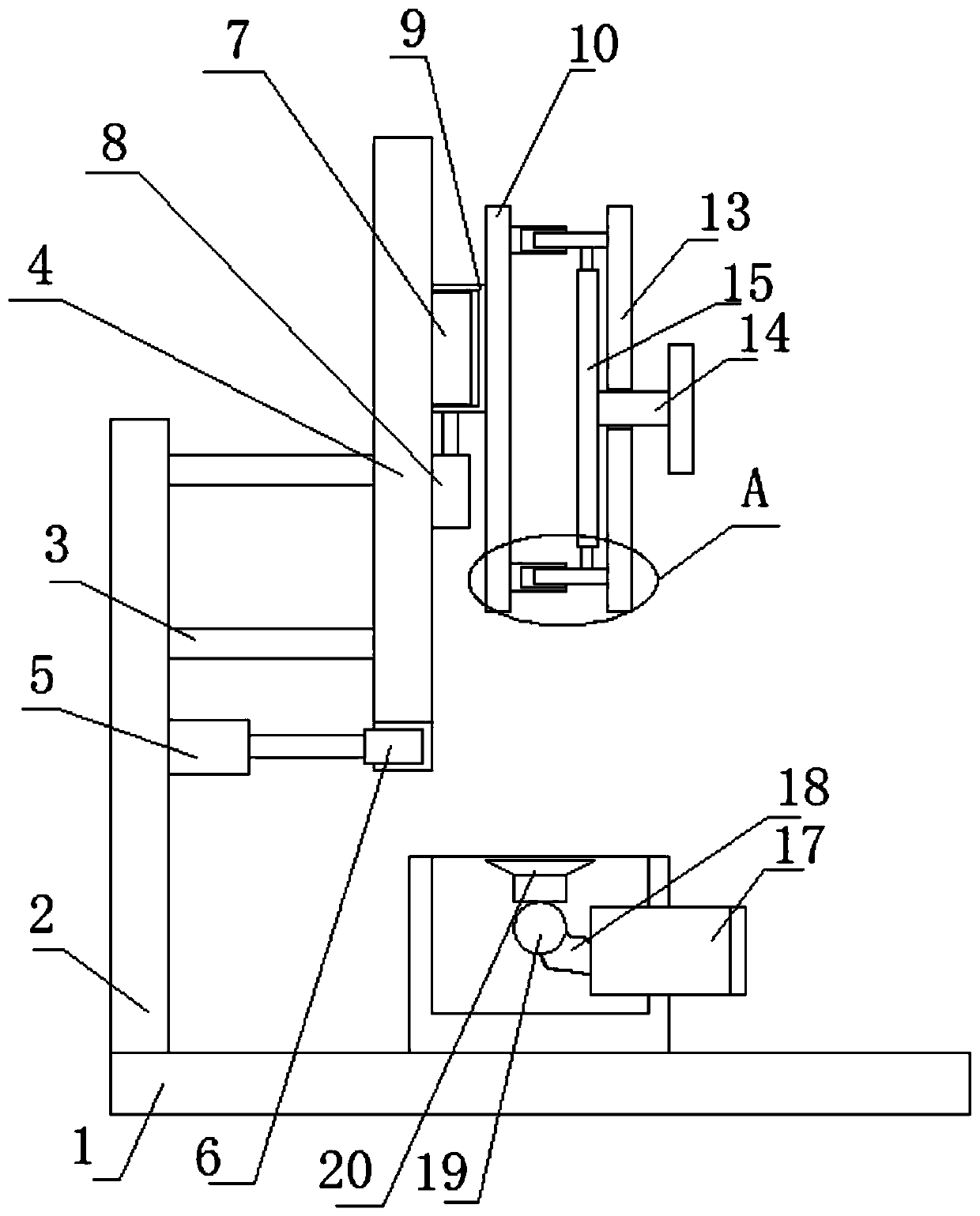
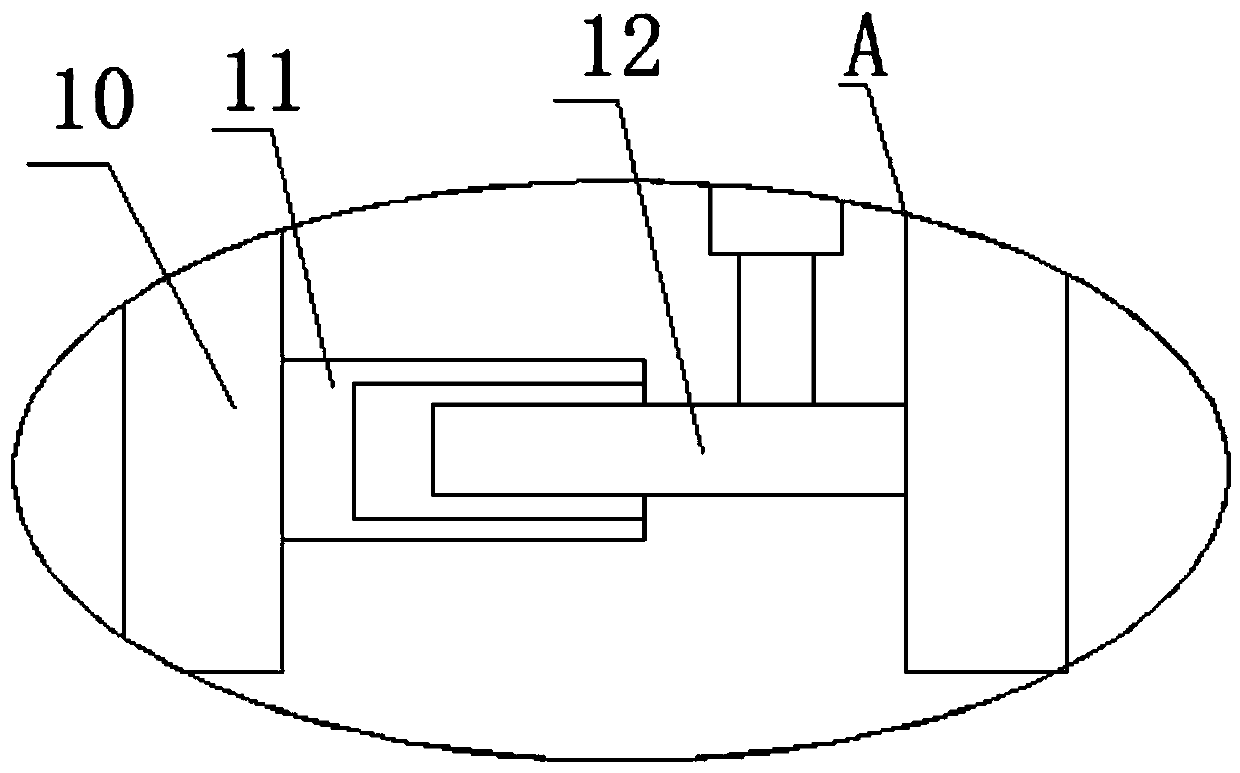
[0020] refer to Figure 1-3 , a wood grooving machine tool, comprising a base 1, a vertical plate 2 is fixedly mounted on one side of the top of the base 1, a mounting plate 4 is fixedly mounted on one side of the vertical plate 2, and a fixed plate 10 is slidably mounted on one side of the mounting plate 4 One side of the fixed plate 10 is slidingly installed with a moving plate 13, one side of the moving plate 13 is threadedly connected with a screw 14, and one end of the screw 14 is rotatably installed with a pressure plate 15, and the other end of the screw 14 runs through the bottom of the moving plate 13. One side extends to the other side of the moving plate 13, and the outer side of the screw rod 14 is screwed to the moving plate 13. The top center of the base 1 is fixed with a collection pool 16, and the inner wall of the collection pool 16 is provided with a sawdust collection assembly. And the collection pool 16 is located directly below the area between the moving ...

Embodiment 2

[0022] Make following further improvement on the basis of embodiment one:

[0023] In the present invention, in order to realize the grooving work of wood conveniently and quickly, one side of the vertical plate 2 is fixedly installed with a cylinder 5, and one end of the output shaft of the cylinder 5 is fixedly installed with a grooving knife 6, and one side of the grooving knife 6 runs through One side of the mounting plate 4 is also located on the same vertical plane as the other side of the mounting plate 4, and one side of the vertical plate 2 is fixedly equipped with a plurality of cross columns 3 arranged in a matrix, and the plurality of horizontal columns 3 are far away from the vertical plane of the vertical plate 2. One end is fixedly installed with one side of the mounting plate 4 .

[0024] In the present invention, in order to realize the lateral movement of the wood, one side of the mounting plate 4 is fixedly equipped with a slide rail 7, one side of the fixed...


PUM


Abstract

The invention belongs to the field of machine tools, and particularly provides a wood grooving machine tool. The problems that an existing wood grooving machine tool cannot collect wood bits generatedby grooving, the wood bits are mixed in the air in the grooving area, body health of a worker is affected, and the machine is not environmentally friendly. The machine tool comprises a base, a vertical plate is fixedly mounted on one side of the top of the base, a mounting plate is fixedly mounted on one side of the vertical plate, a fixed plate is slidingly mounted on one side of the mounting plate, a movable plate is slidingly mounted on one side of the fixed plate, a screw is in threaded connection with one side of the movable plate, one end of the screw is rotatably provided with a pressing plate, compared with a traditional wood grooving machine tool, the wood bits generated in the grooving process can be subjected to unified collection, environment-friendly machining of wood bit grooving is achieved, the wood bits cannot be mixed in the air of the grooving machining area, and work environment of a worker is ensured.

Description

technical field [0001] The invention relates to the technical field of machine tools, in particular to a wood grooving machine tool. Background technique [0002] A machine tool refers to a machine that manufactures a machine, also known as a machine tool or a tool machine, and is customarily referred to as a machine tool. Generally divided into metal cutting machine tools, forging machine tools and woodworking machine tools. There are many ways to process mechanical parts in modern machinery manufacturing. Wood needs to be processed by machine tools in the process of grooving. [0003] Existing wood grooving machine tools cannot collect the sawdust produced by grooving, resulting in the mixing of wood chips in the air in the grooving area, which affects the health of the staff and is not environmentally friendly. Therefore, we propose a wood grooving machine tool that uses to solve the above-mentioned problems. Contents of the invention [0004] The purpose of the pres...

Claims


Application Information

Patent Timeline
IPC IPC(8): B27F5/02B27G3/00
CPCB27F5/02B27G3/00
Inventor 顾琪贲能军惠为东王驰
Owner YANCHENG INST OF IND TECH
Learn More