
Anti-tool-collision digital controlled lathe

A numerical control lathe and anti-collision technology, applied in the field of machine tools, can solve the problems of collision accident, high risk factor, failure of module grinding, etc., and achieve the effect of reducing harmfulness

Inactive Publication Date: 2020-08-25
周书全
View PDF10 Cites 0 Cited by
  • Summary
  • Abstract
  • Description
  • Claims
  • Application Information

AI Technical Summary

Problems solved by technology

[0002] CNC machine tools can better solve complex and precise mold parts processing. Therefore, in mold design, CNC machine tools are the preferred equipment for mold grinding. , if the parameters are adjusted incorrectly, the tool will collide with the module, and the module will fail to polish, and the tool hair will also be damaged. In addition, there are many parts around the tool holder. When the equipment is working, these parts are locks. Stay, when unlocked, these parts will change and collide with the tool. At this time, the tool will be ejected due to the collision, and the risk factor is high. When the mold is clamped, it needs to be clamped with great force. Otherwise, the mold will be tilted, and knife collisions will also occur during work

Method used


Image

  • Anti-tool-collision digital controlled lathe
  • Anti-tool-collision digital controlled lathe
  • Anti-tool-collision digital controlled lathe

Examples


Embodiment 1

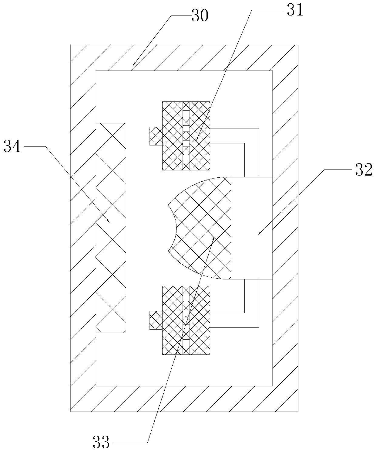
[0028] see Figure 1-Figure 5 , a kind of anti-collision knife numerical control lathe, the present invention provides a kind of anti-collision knife numerical control lathe, aiming at the deficiencies in the prior art, the present invention is realized through the following technical scheme: a kind of anti-collision knife numerical control lathe, its structure includes machine body 1. Sliding door 2, processing box 3, control box 4, base 5, the body 1 is slidably connected with the sliding door 2, the body 1 is mechanically connected with the processing box 3, and the base 5 is installed below the body 1. The right side of the body 1 is provided with a control box 4;

[0029] Described processing box 3 is provided with casing 30, catapult 31, knife rest clamp 32, bumper 33, module folder 34, and the left side of described casing 30 is provided with knife rest clamp 32, and described catapult 31 installs On both sides of the tool post clamp 32, the module clamp 34 is installe...

Embodiment 2

[0038] see Figure 1-Figure 5 , a kind of anti-collision knife numerical control lathe, the present invention provides a kind of anti-collision knife numerical control lathe, aiming at the deficiencies in the prior art, the present invention is realized through the following technical scheme: a kind of anti-collision knife numerical control lathe, its structure includes machine body 1. Sliding door 2, processing box 3, control box 4, base 5, the body 1 is slidably connected with the sliding door 2, the body 1 is mechanically connected with the processing box 3, and the base 5 is installed below the body 1. The right side of the body 1 is provided with a control box 4;

[0039] Described processing box 3 is provided with casing 30, catapult 31, knife rest clamp 32, bumper 33, module folder 34, and the left side of described casing 30 is provided with knife rest clamp 32, and described catapult 31 installs On both sides of the tool post clamp 32, the module clamp 34 is installe...


PUM


Abstract

The invention discloses an anti-tool-collision digital controlled lathe. The anti-tool-collision digital controlled lathe structurally comprises a body, a sliding door, a treatment box, a control boxand a base. The body is in sliding connection with the sliding door, and the body is mechanically connected with the treatment box. The base is mounted below the body, and the control box is arrangedon the right side of the body. The treatment box is provided with a box body, an ejector, a tool rest clamp, a bumper and a module clamp. The tool rest clamp is arranged on the left side of the box body. According to the anti-tool-collision digital controlled lathe, a button block and a front cavity block are in clamped connection, and the rear end of a button structure of the button block protrudes out; when the button block and the front cavity block are clamped, the button block is attached to a fixed block, and the fixed block can be pushed; when the equipment does not work, the button block needs to be moved to the upper portion, the fixed block and the button block are not in contact at this moment, the fixed block is contracted in a telescopic body, and the fixed block cannot be triggered; and the situation that when the equipment does not work, the fixed block is triggered, and an ejection switch is started in advance is avoided.

Description

technical field [0001] The invention relates to the field of machine tools, in particular to an anti-collision tool numerical control lathe. Background technique [0002] CNC machine tools can better solve complex and precise mold parts processing. Therefore, in mold design, CNC machine tools are the preferred equipment for mold grinding. , if the parameters are adjusted incorrectly, the tool will collide with the module, and the module will fail to polish, and the tool hair will also be damaged. In addition, there are many parts around the tool holder. When the equipment is working, these parts are locks. Stay, when unlocked, these parts will change and collide with the tool. At this time, the tool will be ejected due to the collision, and the risk factor is high. When the mold is clamped, it needs to be clamped with great force. Otherwise, the mold will be tilted, and knife collisions will also occur during work. Contents of the invention [0003] Aiming at the deficie...

Claims


Application Information

Patent Timeline
Patent Type & Authority Applications(China)
IPC IPC(8): B24B19/20B24B41/06B24B41/00B24B51/00
CPCB24B19/20B24B41/00B24B41/06B24B51/00
Inventor 周书全
Owner 周书全
Learn More