
Left side plate

A technology of left side plate and support plate, applied in the field of continuous die, can solve the problems of inconvenience of use and affect the replacement efficiency of the left side plate of the continuous die, and achieve the effect of stable structure and easy assembly.

Pending Publication Date: 2020-08-25
青岛创王智能科技有限公司
View PDF0 Cites 0 Cited by
  • Summary
  • Abstract
  • Description
  • Claims
  • Application Information

AI Technical Summary

Problems solved by technology

[0005] The purpose of the present invention is to provide a left side plate to solve the inconvenience of assembling the left side plate of the continuous mold when the current left side plate of the continuous mold proposed by the above-mentioned background technology is in use, which affects the replacement efficiency of the left side plate of the continuous mold. Inconvenience

Method used


Image

  • Left side plate
  • Left side plate
  • Left side plate

Examples


Embodiment Construction

[0026] The following will clearly and completely describe the technical solutions in the embodiments of the present invention with reference to the accompanying drawings in the embodiments of the present invention. Obviously, the described embodiments are only some, not all, embodiments of the present invention. Based on the embodiments of the present invention, all other embodiments obtained by persons of ordinary skill in the art without making creative efforts belong to the protection scope of the present invention.

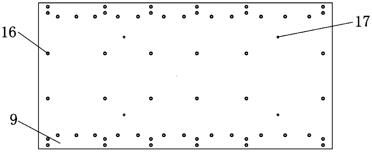
[0027] see Figure 1-6 , the present invention provides a technical solution: a left side plate, including a lower supporting plate 1, a lower cushion block 2, a lower die base 3, a lower base plate 4, a stop plate 5, an upper splint 6, an upper die base 7, Upper cushion block 8, upper supporting plate 9, ejector rod groove 10, ejector rod 11, card slot 12, card block 13, card sleeve 14, elastic card block 15, first bolt groove 16, second bolt groove 17, third...


PUM


Abstract

The invention discloses a left side plate which comprises a lower support plate and a top rod; a lower cushion block is fixed to the upper end of the lower support plate; a lower die holder is fixed to the side, far away from the lower support plate, of the lower cushion block; a lower backing plate is fixed to the side, far away from the lower cushion block, of the lower die holder; a stop baffleis arranged on the top of the lower backing plate; an upper clamping plate is fixed above the stop baffle; an upper die holder is fixed to the side, far away from the stop baffle, of the upper clamping plate; an upper cushion block is fixed to the top of the upper die holder; and an upper support plate is mounted on the side, far away from the upper die holder, of the upper cushion block. The left side plate is provided with the lower support plate and the upper support plate; the lower support plate, the lower cushion block, the lower die holder, the lower backing plate, the stop baffle, theupper clamping plate, the upper die holder, the upper cushin block and the upper support plate are fixedly connected through a first bolt groove, a second bolt groove, a third bolt groove and a fourth bolt groove to form the left side plate, so that the left side plate is steadier in structure and can be assembled and rapidly changed.

Description

technical field [0001] The invention relates to the technical field of continuous molds, in particular to a left side plate. Background technique [0002] The continuous die refers to the cold stamping die in which the press uses strip-shaped stamping raw materials in one stamping stroke, and uses several different stations on a pair of molds to complete multiple stamping processes at the same time. A mold that moves once at a fixed distance until the product is completed. In the assembly of the continuous mold, the left side plate needs to be used. [0003] Although there are many types and quantities of the current continuous form left side panels, there are still certain problems in the existing continuous form left side panels, which bring certain inconvenience to the use of the continuous form left side panels. [0004] When the existing continuous mold left side plate is in use, it is inconvenient to assemble the continuous mold left side plate, which affects the repl...

Claims


Application Information

Patent Timeline
Patent Type & Authority Applications(China)
IPC IPC(8): B21D37/08
CPCB21D37/08
Inventor 佟国栋杜祖椿张晓慧
Owner 青岛创王智能科技有限公司
Learn More