Negative pressure aspirator

The technology of negative pressure suction device and negative pressure generator is applied in the direction of suction container, suction device, hypodermic injection device, etc. It can solve the problems of limited capacity of negative pressure suction device, pollution of operating table, liquid backflow and other problems, and achieve simple insertion The effect of connection

Active Publication Date: 2020-08-25
SHANGHAI CITY JIADING DISTRICT CENT HOSPITAL
View PDF11 Cites 0 Cited by
  • Summary
  • Abstract
  • Description
  • Claims
  • Application Information

AI Technical Summary

Problems solved by technology

When the existing negative pressure suction device is in use, due to the limited capacity of the negative pressure suction device, medical personnel need to replace the suction bag during the operation, and there will be a phenomenon of liquid backflow, which will cause contamination on the operating table and easily cause infection

Method used


Image

  • Negative pressure aspirator
  • Negative pressure aspirator
  • Negative pressure aspirator

Examples


Embodiment 1

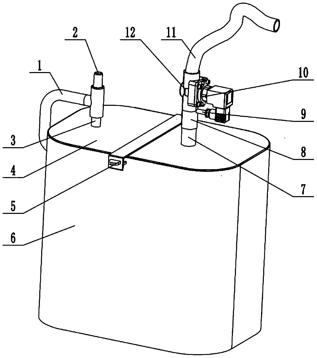
[0031] see Figure 1 to Figure 2 , a negative pressure suction device provided by the present invention includes an anti-reverse valve 12 and a liquid collection bottle 6 . The liquid collecting bottle 6 is made of transparent plastic material, the connecting pipe 1 and the liquid collecting bottle 6 are plugged in, the other end of the connecting pipe 1 is glued to the connecting pipe 2 of the negative pressure generator, and the lower end of the connecting pipe 2 of the negative pressure generator is The negative pressure tube 3 is sealed and connected, and the negative pressure tube 3 and the upper cover 4 of the liquid collection bottle are integrated. A connection buckle 8 is also glued on the liquid collection bottle 6 . The upper end of the anti-reverse valve 12 is provided with a suction pipe 11 , and the lower end of the anti-reverse valve 12 is connected with the liquid collection bottle 6 through the connection buckle 8 . A backstop 10 is provided inside the anti-...

Embodiment 2

[0034] see Figure 3-Figure 12, is a kind of negative pressure suction device that the present invention adds several components on the basis of embodiment 1, comprises anti-return valve 12 and liquid collection bottle 6, and the upper end of anti-return valve 12 is provided with suction tube 11 , the inside of the anti-reverse valve 12 is provided with a checker 10, the bottom of the checker 10 is provided with a third piston 13, the left side of the third piston 13 is provided with a spring, and the left side of the spring is provided with an air pressure valve 14, the second The bottom of the three pistons 13 is provided with a locking device 9, the locking device 9 includes a first piston 91 and a locking rod 92, the left side of the first piston 91 is provided with a locking rod 92; the bottom of the locking rod 92 is provided with a connecting card Buckle 8, the left side of the connection buckle 8 is provided with a liquid inlet pipe 7, and the bottom of the liquid inle...


PUM


Abstract

The invention discloses a negative pressure aspirator. The negative pressure aspirator comprises an anti-check valve and a liquid collecting bottle, wherein a suction tube is arranged at the upper endof the anti-check valve; check devices are arranged in the anti-check valve; each check device comprises a second piston and a screw rod, and the screw rod is arranged at the left end of the second piston; third pistons are arranged below the check devices; lockers are arranged below the third pistons; each locker comprises a first piston and a locking rod; and the anti-check valve is arranged between the suction tube and the liquid collecting bottle. The plurality of pistons, check devices and locking rods are arranged in the anti-check valve; linkage control is conducted on the check devices and the locking rods by means of a negative pressure environment in the liquid collecting bottle; in the negative pressure environment, the check devices can be opened, so that the suction tube cansuck liquid such as blood into the liquid collecting bottle; and when the negative pressure environment does not exist, the check devices can be closed immediately, so that the liquid in the suction tube cannot flow back to pollute an operating table to cause patient infection when a suction bag is replaced.

Description

technical field [0001] The invention relates to the technical field of medical devices, in particular to a negative pressure suction device. Background technique [0002] The negative pressure suction device is a tool that creates the negative pressure state of its suction head by a certain method, and the material outside the suction head is squeezed to the suction head to complete the "suction" effect. The negative pressure suction device consists of a pressure regulator, a liquid collection bottle, hose etc. There are two hose ports on the liquid collection bottle, one is connected to the negative pressure terminal and the other is connected to the working chamber. When the negative pressure terminal is connected, a negative air pressure will be generated in the liquid collection bottle, and the negative pressure will guide dirt, such as blood, phlegm, etc., into the liquid collection bottle from another hose. When the height of the liquid in the liquid collection bottl...

Claims


Application Information

Patent Timeline
IPC IPC(8): A61M1/00A61M39/24
CPCA61M1/0023A61M1/0001A61M39/24A61M1/84
Inventor 唐晓燕
Owner SHANGHAI CITY JIADING DISTRICT CENT HOSPITAL
Why Eureka
Try Eureka