Intermediate case structure

An intermediary and casing technology, applied in mechanical equipment, engine components, gas turbine devices, etc., can solve problems such as flow channel layout damage, occupying a large space, and limiting the layout space of duct conversion mechanisms

Active Publication Date: 2020-08-21
AECC SHENYANG ENGINE RES INST
View PDF7 Cites 4 Cited by
  • Summary
  • Abstract
  • Description
  • Claims
  • Application Information

AI Technical Summary

Problems solved by technology

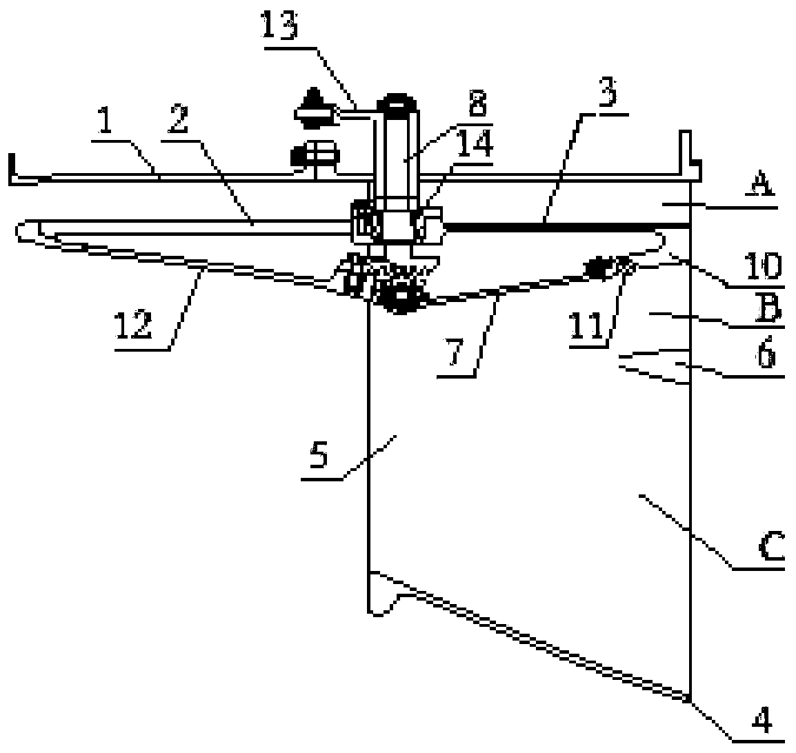
[0004] The intermediate casing with three-duct structure has a more complicated structure than the double-duct intermediate casing, and its duct conversion mechanism mostly adopts the form of connecting rod transmission. It is relatively simple, but has a relatively large number of parts, and needs to occupy a large space, and needs to reserve a large space for its action, and the intermediary casing of the three-duct structure has limited the capacity due to the addition of the third duct. In this case, setting up the duct conversion mechanism driven by the connecting rod will easily damage the layout of the flow channel and reduce the performance of the engine.

Method used


Image

  • Intermediate case structure
  • Intermediate case structure
  • Intermediate case structure

Examples


Embodiment Construction

[0046] In order to make the technical solution of the present application and its advantages clearer, the technical solution of the present application will be further clearly and completely described in detail below in conjunction with the accompanying drawings. It can be understood that the specific embodiments described here are only part of the application Examples are only used to explain the present application, not to limit the present application. It should be noted that, for the convenience of description, only the parts related to the present application are shown in the drawings, and other relevant parts can refer to the general design. In the case of no conflict, the embodiments in the application and the technologies in the embodiments Features can be combined with each other to obtain new embodiments.

[0047] In addition, unless otherwise defined, the technical terms or scientific terms used in the description of the application shall have the usual meanings und...


PUM


Abstract

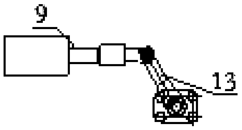
The invention relates to an intermediate case structure which comprises an intermediate case, a front shunting ring, an outer ring, an inner ring, a plurality of support plates, a rear shunting ring,a plurality of duct converting valves, a plurality of rotary shafts and an actuating mechanism; the front shunting ring is arranged in the intermediate case; the outer ring is in butt joint with the front shunting ring; the inner ring is arranged in the outer ring; one end of each of the support plates is connected with the intermediate case, the other end thereof is connected with the inner ring,and a gap is formed in the side, back on to the inlet end of the intermediate case; the rear shunting ring is clamped in all gaps and is positioned between the outer ring and the inner ring; each ofthe duct converting valves is hinged to the front shunting ring, and conical gears are arranged on the duct converting valves; one conical gear is arranged at one end of each of the rotary shafts; theconical gear on each of the rotary shafts is meshed with the conical gear on the corresponding duct converting valve; the actuating mechanism is arranged on the intermediate case and is connected with the other end of each of the rotary shafts to drive all rotary shafts to rotate, so that the duct converting valves rotate, and the intermediate case structure has the outer duct closing state and the outer duct opening state; when the intermediate case structure is in the outer duct closing state, the duct converting valves are in lap joint with the rear shunting ring; and when the intermediatecase structure is in the outer duct opening state, the duct converting valves are separated from the rear shunting ring.

Description

technical field [0001] The application belongs to the technical field of intermediate casing structure design, and in particular relates to an intermediate casing structure. Background technique [0002] The traditional aero-engine intermediary case is mostly a double-duct structure, which divides the airflow channel in the intermediary case into inner duct and outer duct through a shunt ring, and controls the inner duct and outer duct through the corresponding duct conversion mechanism. status of circulation. [0003] At present, with the development of aviation technology, an adaptive variable cycle engine is proposed, which adds an independent third duct by adding a shunt ring and its corresponding structure on the basis of the double-duct intermediary casing. A three-channel structure is formed in the box, so that the air flow can be better adjusted and controlled, and the overall performance of the engine can be improved. [0004] The intermediate casing with three-du...

Claims


Application Information

Patent Timeline
IPC IPC(8): F02C7/04F02C7/057F02K3/075F02K3/077
CPCF02C7/04F02C7/057F02K3/075F02K3/077
Inventor 张弛门玉宾王坤
Owner AECC SHENYANG ENGINE RES INST
Why Eureka
Try Eureka