Flexible anti-collision sheath of telegraph pole

A technology for anti-collision sheaths and utility poles, applied in roads, buildings, road safety devices, etc., can solve the problems of poor toughness of utility poles and the inability to improve the ability of utility poles to resist impact, so as to reduce hard injuries and reduce collisions The effect of broken risk

Active Publication Date: 2020-08-21
国网黑龙江省电力有限公司佳木斯供电公司 +1
View PDF6 Cites 2 Cited by
  • Summary
  • Abstract
  • Description
  • Claims
  • Application Information

AI Technical Summary

Problems solved by technology

[0002] It is well known that power transmission requires the use of wires. In order to prevent the wires from electrifying people and make the wires turn as little as possible, the wires are mainly propped up in mid-air by utility poles. Or the utility poles near the parking space are more likely to be hit when the car is driving or parking. Since many utility poles use steel bars and cement as the main base material, the toughness of the utility poles is poor while achieving the purpose of support, especially cement utility poles. It is easy to break after being hit, and further cause power outage accidents in nearby factories, mines, enterprises, institutions or residents. In order to overcome this drawback, many utility poles are wrapped with eye-catching fluorescent materials, but this method is difficult to prevent the utility poles from being damaged. The occurrence of collision accidents cannot improve the ability of utility poles to resist impact

Method used


Image

  • Flexible anti-collision sheath of telegraph pole
  • Flexible anti-collision sheath of telegraph pole
  • Flexible anti-collision sheath of telegraph pole

Examples


Embodiment Construction

[0025] The present invention is further described below in conjunction with embodiment; The following embodiment is not for the limitation of the present invention, only as the mode of supporting the realization of the present invention, any equivalent structural replacement within the technical framework disclosed in the present invention, all is the present invention. the scope of protection of the invention;

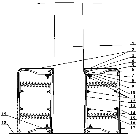
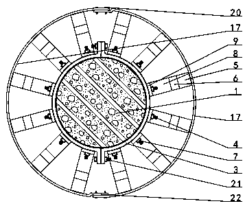
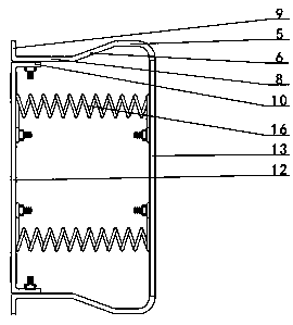
[0026] combined with Figure 1-7 The flexible anti-collision sheath of the utility pole described in includes the upper hoop 3, the lower hoop 19, the outer long vertical plate 13, the inner long vertical plate 12, the spring 16 and the outer cylinder 17, which are wrapped on the double semicircular structure. The outer edge surface of hoop 3 and lower hoop 19 is provided with a plurality of radially distributed screw rods A4, the upper hoop 3 is arranged on the lower outer edge surface of utility pole 1, and the lower hoop 19 is arranged on the lower end outer edge o...


PUM


Abstract

Provided in the invention is a flexible anti-collision sheath of a telegraph pole, which relates to an anti-collision sheath of a telegraph pole. A plurality of screw rods A (4) are arranged on the outer edge surfaces of an upper hoop (3) and a lower hoop (19); inward horizontal plates (8) are arranged at the upper end and the lower end of an outer long vertical plate (13) respectively, the upperend and the lower end of an inner long vertical plate (12) are fixedly connected to the inner ends of two horizontal plates of the outer long vertical plate, and at least one spring (16) is arranged between the middle of the outer long vertical plate and the middle of the inner long vertical plate. A short vertical plate (9) is arranged above the inner end of each horizontal plate; a downward short vertical plate is arranged at the lower part of the inner end of each horizontal plate to form a set of flexible anti-collision mechanisms, a plurality of upward short vertical plate unthreaded holes (24) of the flexible anti-collision mechanisms sleeve the screw rods A of the upper hoop and then are locked by nuts (7) to form a flexible anti-collision sheath at the outer lower part of a telegraph pole (1), and an outer cylinder (17) wraps the flexible anti-collision sheath. The springs are used for supporting the outer long vertical plate and the inner long vertical plate, and flexible collision avoidance of the telegraph pole is achieved through the springs and the outer long vertical plate .

Description

【Technical field】 [0001] The invention relates to an anti-collision sheath for an electric pole, in particular the invention relates to a flexible anti-collision sheath for an electric pole. 【Background technique】 [0002] It is well known that power transmission requires the use of wires. In order to prevent the wires from electrifying people and make the wires turn as little as possible, the wires are mainly propped up in mid-air by utility poles. Or the utility poles near the parking space are more likely to be hit when the car is driving or parking. Since many utility poles use steel bars and cement as the main base material, the toughness of the utility poles is poor while achieving the purpose of support, especially cement utility poles. It is easy to break after being hit, and further cause power outage accidents in nearby factories, mines, enterprises, institutions or residents. In order to overcome this drawback, many utility poles are wrapped with eye-catching fluo...

Claims


Application Information

Patent Timeline
Patent Type & Authority Applications(China)
IPC IPC(8): E01F15/14
CPCE01F15/141E01F15/146
Inventor 潘家祥
Owner 国网黑龙江省电力有限公司佳木斯供电公司
Why Eureka
Try Eureka