
Binding machine

A technology for a bundling machine and bundling wire, which is applied to bundling objects, bundling materials, and parts of bundling machinery, etc., can solve the problems of easy entanglement of bundling wires, poor delivery of bundling wires, detachment of bundling wires, etc. Poor delivery effect

Active Publication Date: 2020-08-21
MAX CO LTD
View PDF10 Cites 0 Cited by
  • Summary
  • Abstract
  • Description
  • Claims
  • Application Information

AI Technical Summary

Problems solved by technology

If the amount of deflection of the binding wire at the portion between the reel and the binding wire conveying unit increases, the binding wire may be bent called buckling, and the binding wires are likely to be entangled with each other, causing poor feeding of the binding wire. , Reasons for reloading of unusable binding wire removed
In addition, if the amount of deflection of the binding wire increases, the binding wire will easily come off from the flange portion of the reel to the outside of the reel.

Method used


Image

  • Binding machine
  • Binding machine
  • Binding machine

Examples


Embodiment Construction

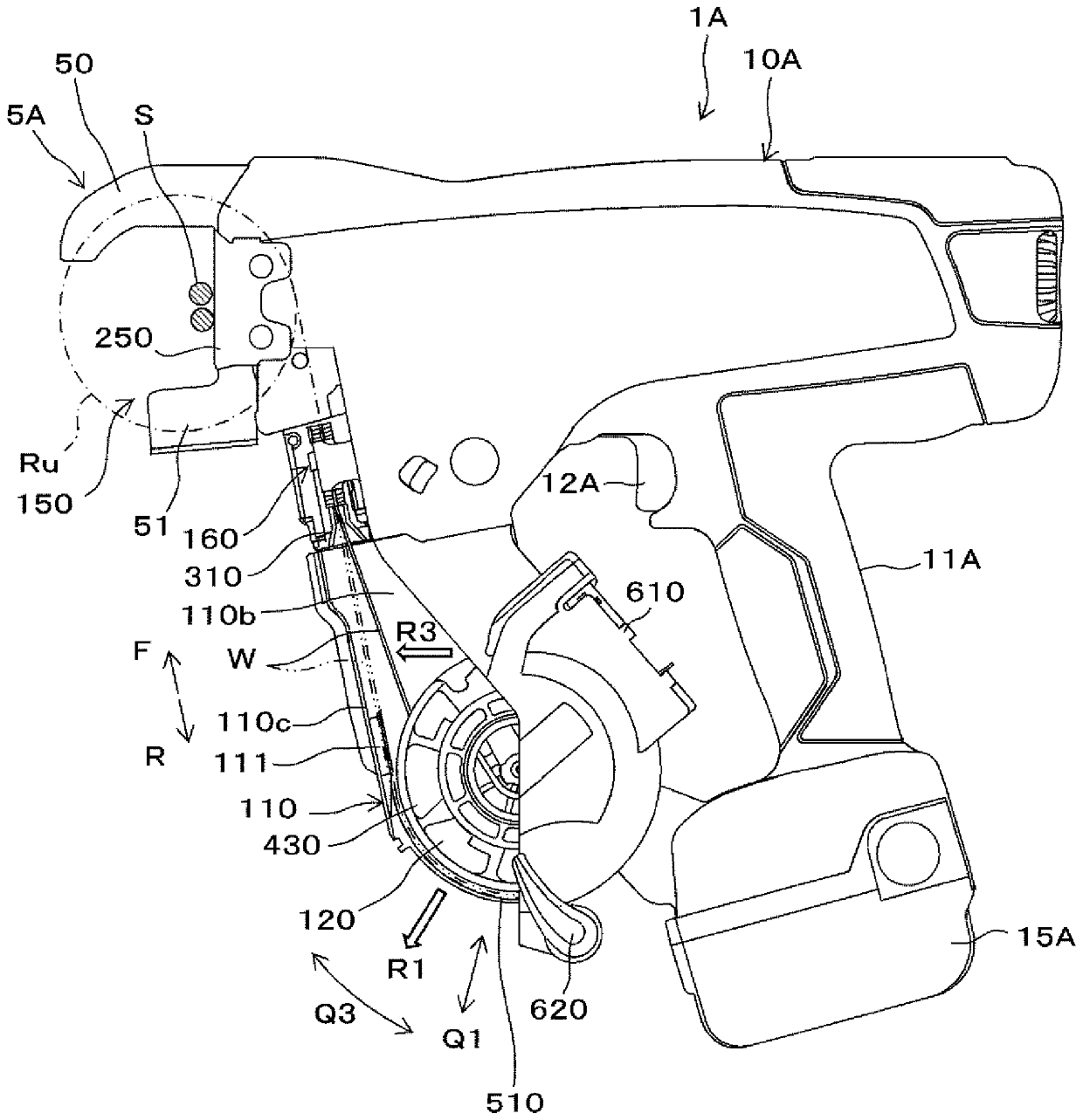
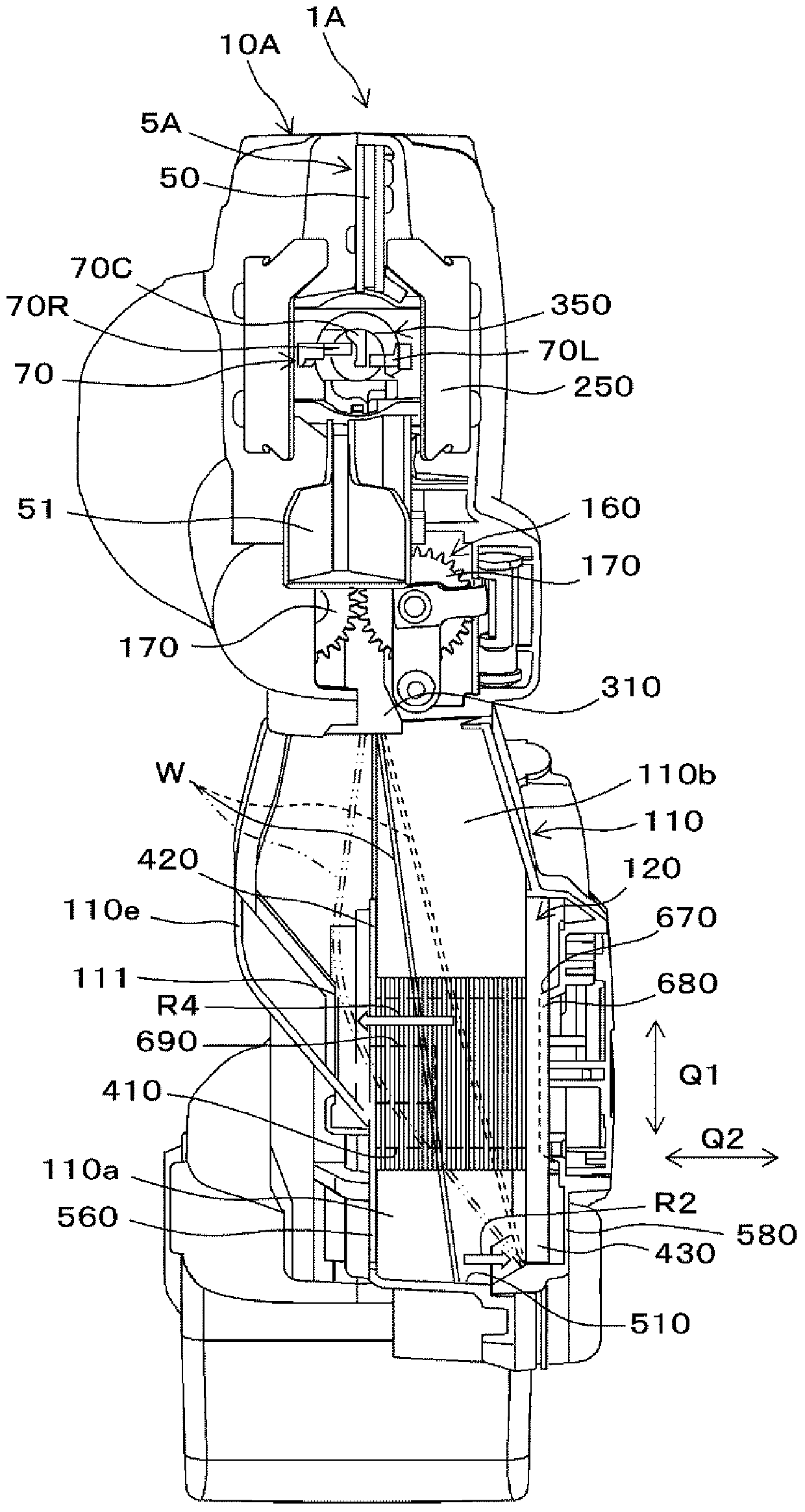
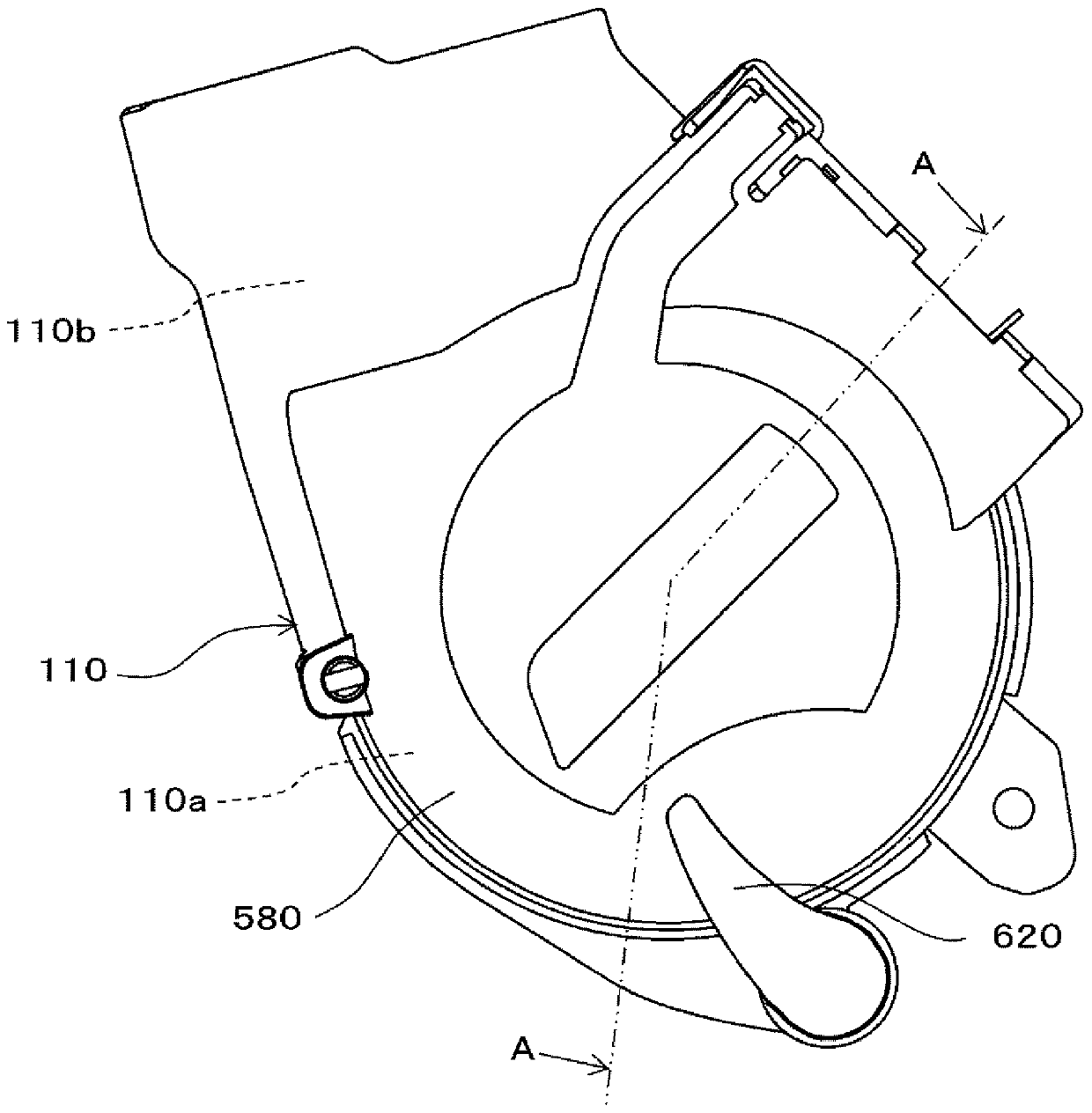
[0029] Embodiments of the binding machine of the present invention will be described below. Figure 1 to Figure 10 It is a figure for demonstrating this embodiment.

[0030]

[0031] Hereinafter, the structure will be described. Such as figure 1 side view of figure 2 As shown in the front view of , for example, a reinforcing bar binding machine (binding machine) 1A is used to bind binding objects (hereinafter referred to as reinforcing bars S) such as steel bars and electric wires at a construction site. This reinforcing bar binding machine 1A feeds the binding wire W in the forward direction indicated by the arrow F, and crimps the binding wire W while imparting an arcuate bending tendency to form a ring Ru surrounding the reinforcement S. Next, the binding wire W is fed in the reverse direction indicated by the arrow R to pull the binding wire W back, and the binding wire W is cut after the binding wire W formed into a ring Ru is wound around the reinforcing bar S. Ne...


PUM


Abstract

The invention provides a binding machine capable of suppressing the amount of deflection of a binding wire. A binding machine includes: an accommodation portion (110) accommodating a reel (120) aroundwhich a wire (W) is wound; a wire feeding portion (160) configured to feed the wire (W) in a forward direction, winds the wire around a binding object, feeds the wire (W) in a reverse direction, andwraps the wire around the binding object. The accommodation portion (110) accommodates the reel (120) such that the reel is offset in one direction along an axial direction of the reel (120) with respect to the wire feeding portion (160). The binding machine further includes a restricting portion (111), in a wire passage (110b) between the reel (120) accommodated in the accommodation portion (110)and the wire feeding portion (160), which protrudes inward of the accommodation portion and has a restricting surface with which the wire (W) bent in the other direction along the axial direction ofthe reel (120) between the reel (120) and the wire feeding portion (160) comes in contact.

Description

technical field [0001] The invention relates to a binding machine for binding binding objects such as steel bars with binding wires. Background technique [0002] Conventionally, a binding machine called a reinforcing bar binding machine has been proposed that winds a binding wire around two or more steel bars, twists the wound binding wire, and binds the two or more steel bars. [0003] A conventional steel bar binding machine has a structure in which a binding wire is conveyed by a binding wire conveyance part and wound around a steel bar, and then the binding wire is twisted to perform binding. For such a reinforcing bar binding machine, the following reinforcing bar binding machine has been proposed: after the binding wire is wound around the reinforcing bar, the binding wire is wound around the reinforcing bar in a close-fitting manner and cut, and one end side of the binding wire is The part intersecting with the other end side is twisted and the reinforcement is bund...

Claims


Application Information

Patent Timeline
Patent Type & Authority Applications(China)
IPC IPC(8): B65B13/02B65B13/04B65B13/18B65B13/28E04G21/12
CPCB65B13/025B65B13/04B65B13/285B65B13/18E04G21/123B21F7/00B21F15/04
Inventor 吉田祐介石黑博树滨野晃史笠原章
Owner MAX CO LTD
Learn More