
Battery charging seat

A battery charging and charging stand technology, which is applied to different battery charging, battery circuit devices, arrangement of multiple synchronous batteries, etc., can solve the problems of inconvenient installation and replacement, and can only be used by one battery, so as to achieve simple structure, Ease of installation and maintenance

Pending Publication Date: 2020-08-18
成都成广电视设备有限公司
View PDF1 Cites 0 Cited by
  • Summary
  • Abstract
  • Description
  • Claims
  • Application Information

AI Technical Summary

Problems solved by technology

[0003] The object of the present invention is to provide a battery charging stand with a number of charging slots evenly arranged to accommodate the battery to be charged and the battery to be charged in order to solve the problems of inconvenient installation and replacement and the use of only one battery in the prior art. The space can be adjusted according to the length of the battery, and the expansion and contraction of the elastic member drives the moving plate to adjust the size of the accommodation space; the second cavity under each charging slot and the first cavity in the seat for laying the charging circuit are connected to each other, and can be adjusted according to Charging requirements Flexible installation and replacement of the charging circuit, capable of charging different types of batteries with positive and negative poles at the same end

Method used


Image

  • Battery charging seat
  • Battery charging seat
  • Battery charging seat

Examples


Embodiment 1

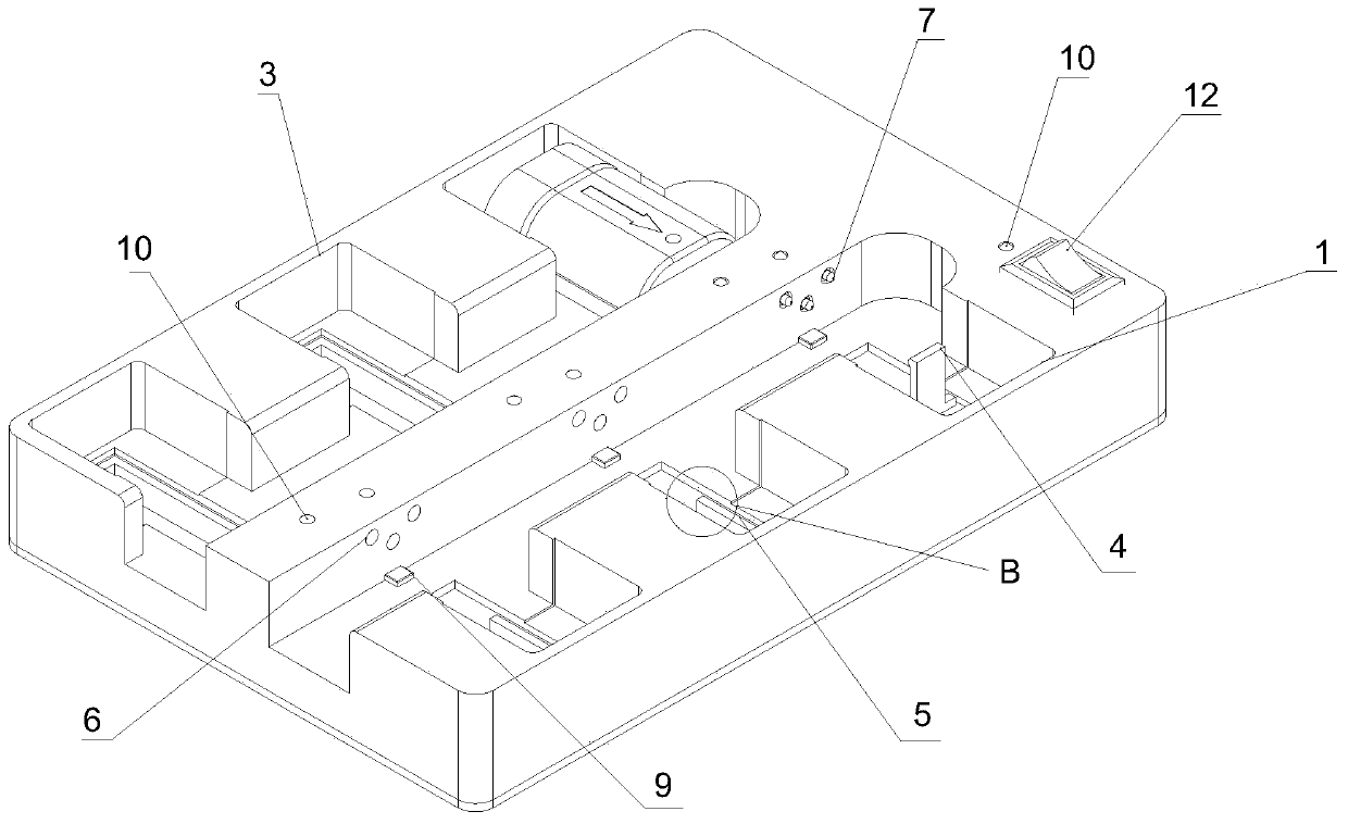
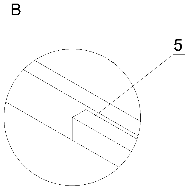
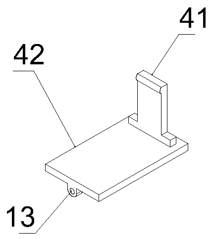
[0040] refer to Figure 1-Figure 6 , a battery charging base, including a base body 1 and a base plate 2, the base plate 2 is fixedly connected with the base body 1 through bolts 16, the base body 1 is provided with a first cavity 17, and the first cavity 17 is provided with a charging current There are several charging slots 3 evenly distributed on the base body 1. In the charging base of this embodiment, the base body 1 has 6 charging slots 3. The six charging slots 3 are distributed in a staggered manner, and the charging slots 3 can be any suitable The shape of the battery to be charged, the charging slot 3 in this embodiment is a rectangle. A charging contact hole 6 is provided on the seat body 1 at a position corresponding to the charging slot 3 for detachably setting the charging contact 7; the charging contact 7 includes a first charging contact, a second charging contact and a third contact , the first charging contact and the second charging contact are both electri...


PUM


Abstract

The invention discloses a battery charging seat. The battery charging seat comprises a seat body and a bottom plate, and the base body and the bottom plate are detachably connected through bolts. A plurality of charging grooves are uniformly formed in the seat body; a charging contact is arranged at the position, corresponding to the seat body, of the charging groove; a chute is formed in the portion, below the charging groove, of the second cavity, the chute is in sliding connection with a movable plate, the movable plate is connected with the base body through an elastic piece, the space forfixing a battery to be charged in the charging groove can be changed, a first cavity is formed in the base body, a charging loop can be laid, and the first cavity and the second cavity are communicated with each other. The multiple charging grooves are formed in the base body, multiple batteries can be charged at the same time, the battery fixing space can be adjusted through stretching of the elastic piece, and a charging loop is easy and convenient to lay.

Description

technical field [0001] The invention relates to the technical field of battery charging, in particular to a battery charging stand. Background technique [0002] There are many types of existing rechargeable batteries with different sizes and lengths, and the charging bases for charging them are also of various specifications. Different types of batteries require different charging bases, which brings manufacturing and after-sales problems to manufacturers. Especially for rechargeable batteries that have been modified but not significantly modified, the size is lengthened or shortened due to the capacity, and the original charging stand can no longer be used due to the lengthening or shortening of the battery. The invention with the patent number CN201210132502.0 discloses a battery charger, which adopts a sliding rail movable device, so that the fixed battery charging space can be changed with the expansion and contraction of the traction spring, so as to charge batteries ...

Claims


Application Information

Patent Timeline
Patent Type & Authority Applications(China)
IPC IPC(8): H02J7/00
CPCH02J7/00047H02J7/0013H02J7/0042H02J7/0045H02J7/0047
Inventor 廖胡娜万明杨毛昆沈亮
Owner 成都成广电视设备有限公司
Learn More