Power device for driving lens barrel of projection lens group to rotate

A technology of projection lens and power device, which is applied in signal devices, lighting devices, components of lighting devices, etc., and can solve the problems of long overall length and loud noise of geared motors

Pending Publication Date: 2020-08-18
广州市火焰光电子科技有限公司
View PDF0 Cites 0 Cited by
  • Summary
  • Abstract
  • Description
  • Claims
  • Application Information

AI Technical Summary

Problems solved by technology

[0005] The main technical problem to be solved by the present invention is to provide a power device for driving the rotation of the lens barrel of the projection lens group, which solves the problem that the overall length of the reduction motor is relatively long due to the fact that the motor and the planetary gear set are mostly directly connected axially together. The problem of long length, and the problem of loud noise caused by geared motors mainly relying on gears meshing to transmit energy during the entire energy transmission process

Method used


Image

  • Power device for driving lens barrel of projection lens group to rotate
  • Power device for driving lens barrel of projection lens group to rotate
  • Power device for driving lens barrel of projection lens group to rotate

Examples


Embodiment 1

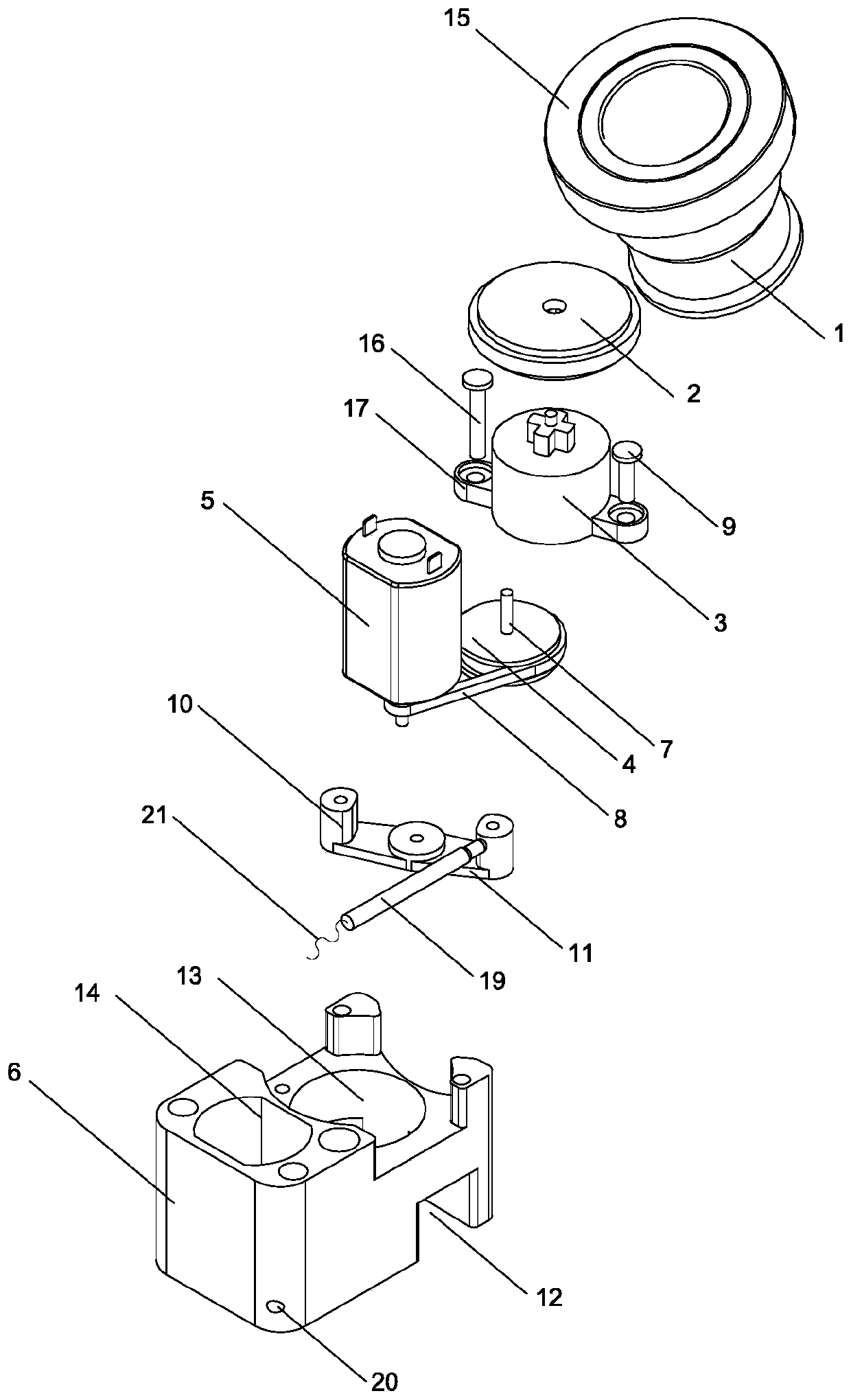
[0025] see figure 1 , figure 1 It is a schematic diagram of the structural principle of the first preferred embodiment of a power device for driving the rotation of the lens barrel of the projection lens group in the present invention. Such as figure 1 As shown, the power device used to drive the rotation of the projection lens group lens barrel in this embodiment includes a projection rotation device, a coupling rubber wheel 2, a planetary gear reduction box 3 with a planetary gear set inside, a pulley 4, a DC motor 5, The transmission structure fixed bracket 6, the first installation groove 13 and the second installation groove 14 placed on the transmission structure fixed bracket 6 for installing the planetary gear reducer 3 and the DC motor 5 respectively, are used to connect the DC motor 5 motor shaft The belt 8 of the pulley 4, the pulley fixed bracket, the third installation groove 12 for installing the pulley fixed bracket placed at the bottom of the transmission str...

Embodiment 2

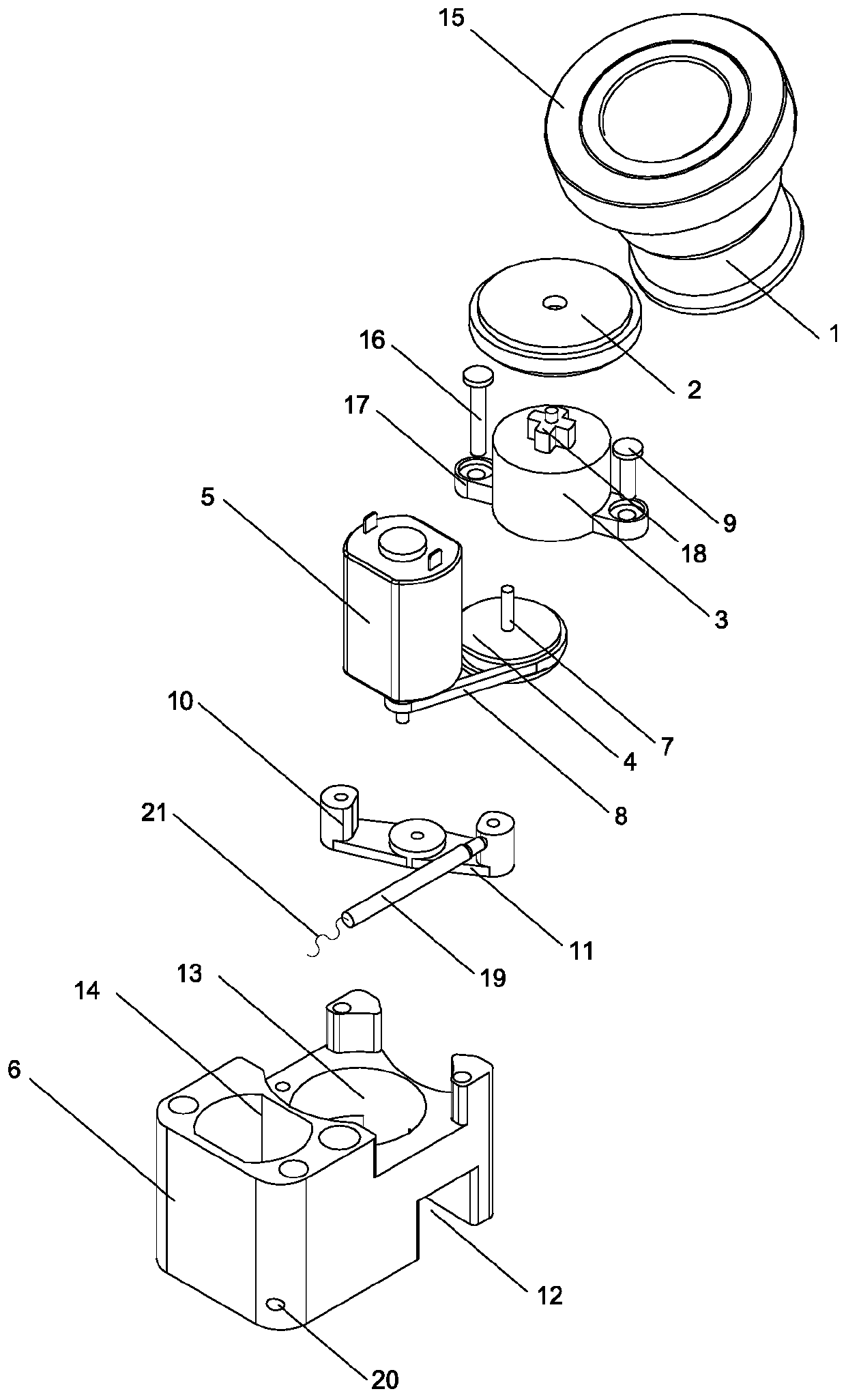
[0047] see figure 2 , figure 2 It is a schematic diagram of the structure principle of the second preferred embodiment of the power device for driving the rotation of the lens barrel of the projection lens group. in, figure 2 The power unit shown for driving the rotation of the lens barrel of the projection lens group is composed of figure 1 The power device shown for driving the rotation of the lens barrel of the projection lens group is optimized.

[0048] and figure 1 Compared with the power device used to drive the rotation of the lens barrel of the projection lens group shown, figure 2 The top of the planetary gear reduction box 3 for driving the rotation of the projection lens group lens barrel is provided with a cross-shaped gear shaft 18, and the bottom end of the coupling rubber wheel 2 is provided with a cross-shaped groove meshing with the cross-shaped gear shaft 18. The belt pulley center shaft 7 is connected with the cross-shaped groove and the coupling r...


PUM


Abstract

The invention provides a power device for driving a lens barrel of a projection lens group to rotate. The device comprises a projection rotation device, a coupling rubber wheel, a planetary gear speedreduction box internally provided with a planetary gear set, a belt pulley, a direct current motor, a transmission structure fixing support, a first installation groove and a second installation groove which are used for installing the planetary gear speed reduction box and the direct current motor respectively, a belt, a belt wheel fixing support, a third installation groove which is used for installing the belt wheel fixing support, a belt wheel center shaft, an automatic gap adjusting device, and a channel arranged in the transmission structure fixing support and used for installing the automatic gap adjusting device. According to the power device for driving the lens barrel of the projection lens group to rotate, the problem that the overall length of an existing gear motor is large due to the fact that most of the motor and planetary gear sets are directly and axially connected into a whole is solved, and the problem that noise is large due to the fact that the gear motor mainlyrelies on gear engagement to transmit energy in the whole energy transmission process is solved.

Description

technical field [0001] The invention relates to the technical field of power devices, in particular to a power device for driving the rotation of a lens barrel of a projection lens group. Background technique [0002] At present, the projection lamps used in automobiles on the market usually have two projection effects: one is to project a static pattern through a fixed lens; the other is to install a permanent magnet synchronous motor (such as a 220v AC low-speed permanent magnet motor ) to drive the lens rotating part to rotate through a transmission mechanism such as a belt to project a dynamic pattern. [0003] But in practice, it is found that most of the patterns projected through the fixed lens are only static patterns, which generally have the disadvantages of monotonous patterns and lack of aesthetic feeling; and the common geared motors on the market, such as the m10 small gear reducer, mostly combine the motor and The planetary gear sets are directly connected ax...

Claims


Application Information

Patent Timeline
Patent Type & Authority Applications(China)
IPC IPC(8): F21S41/63F21S41/683F21V14/06F21V14/08F21W102/20
CPCF21S41/635F21S41/683F21V14/06F21V14/08F21W2102/20
Inventor 朱志坤刘拮畅
Owner 广州市火焰光电子科技有限公司
Why Eureka
Try Eureka