Projection imaging device

An imaging device and projection technology, which is applied in projection devices, optics, instruments, etc., can solve problems such as the inability to meet the requirements of miniaturization and small volume, the limited compression of projection lenses and projection imaging devices, etc., so as to reduce the difficulty of design and collect light The effect of reducing the requirement and shortening the distance

Pending Publication Date: 2020-11-17
QINGDAO HISENSE LASER DISPLAY CO LTD
View PDF4 Cites 0 Cited by
  • Summary
  • Abstract
  • Description
  • Claims
  • Application Information

AI Technical Summary

Problems solved by technology

[0007] In related technologies, the compression of the projection lens and the projection imaging device is very limited, which cannot meet the requirements of miniaturization and small volume

Method used


Image

  • Projection imaging device
  • Projection imaging device
  • Projection imaging device

Examples


Embodiment Construction

[0050] In order to make the purpose, technical solution and advantages of the present application clearer, the implementation manners of the present application will be further described in detail below in conjunction with the accompanying drawings.

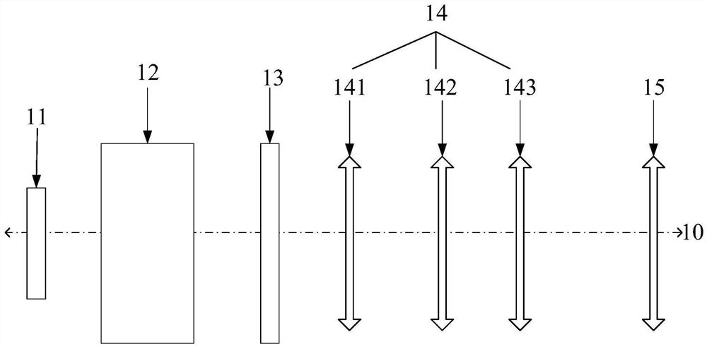
[0051] figure 1It is a structural schematic diagram of a projection imaging device in the related art. The projection imaging device 10 includes a light valve 11 , a total reflection prism 12 , a vibrating mirror 13 , a refracting mirror group 14 and a reflecting mirror group 15 . The refracting mirror group 14 includes a first mirror group 141 , a second mirror group 142 and a third mirror group 143 arranged in sequence along the optical axis length direction 10 . The light emitted by the light source passes through the light valve 11 and the total reflection prism 12 and then goes to the vibrating mirror 13, and the light passing through the vibrating mirror 13 is directed to the refracting mirror group 14 through the vibration...


PUM


Abstract

The invention discloses a projection imaging device, and belongs to the technical field of imaging. The imaging device comprises a light valve and a projection lens, the projection lens comprises a planar reflector group, a refractor group and a curved reflector group, the planar reflector group comprises at least one reflector, and the planar reflector group is arranged between a part of lenses of the refractor group and the curved reflector group; an image light beam emitted by the light valve is transmitted by at least part of lenses of the refractor group, then enters the plane reflector group, is reflected by the plane reflector group at least once and then enters the curved reflector group, and the curved reflector group is used for reflecting the image light beam and imaging the image light beam on a screen. The light source path is changed after the light source is reflected through the reflector, the optical axes of the two lens sets are not located on the same straight line,and the length of the projection lens is reduced. The problem that projection equipment is long in length in the prior art is solved, and the effect of reducing the length of the projection equipmentis achieved.

Description

[0001] This application requires the Chinese patent application with the application number 201910398141.6 and the application name "Projection Lens and Projection Imaging System" submitted on May 14, 2019 and the application number 202010177890.9 submitted on March 13, 2020 and the application name " The priority of the Chinese patent application of "Projection Lens and Projection Device", the entire content of which is incorporated in this application by reference. technical field [0002] The present application relates to the field of imaging technology, in particular to a projection imaging device. Background technique [0003] A projection imaging device is a device that projects an image onto a screen. [0004] At present, a projection imaging device generally includes: a light source, an optical machine and a projection lens. The light source is used to provide illumination for the optical-mechanical part. The light source can be a monochromatic laser light source t...

Claims


Application Information

Patent Timeline
Patent Type & Authority Applications(China)
IPC IPC(8): G03B21/14G03B21/28G02B13/00G02B26/08
CPCG02B13/0055G02B13/0065G02B26/0816G02B26/0875G03B21/142G03B21/28G02B13/00G02B26/08G03B21/14
Inventor 李晓平钟强阴亮
Owner QINGDAO HISENSE LASER DISPLAY CO LTD
Why Eureka
Try Eureka