Magnetic pump

A technology of magnetic pump and pump cover, applied in the direction of pumps, pump devices, pump components, etc., can solve the problems of adverse effects, high temperature of transmission medium, etc.

Active Publication Date: 2020-08-18
福建省福安市力德泵业有限公司
View PDF5 Cites 1 Cited by
  • Summary
  • Abstract
  • Description
  • Claims
  • Application Information

AI Technical Summary

Problems solved by technology

[0006] The technical problem to be solved by the present invention is: how to improve the structure of the magnetic pump to avoid the adverse effects of the traditional magnetic pump structure due to the high or low temperature of the transmission medium

Method used


Image

  • Magnetic pump
  • Magnetic pump
  • Magnetic pump

Examples


Embodiment 1

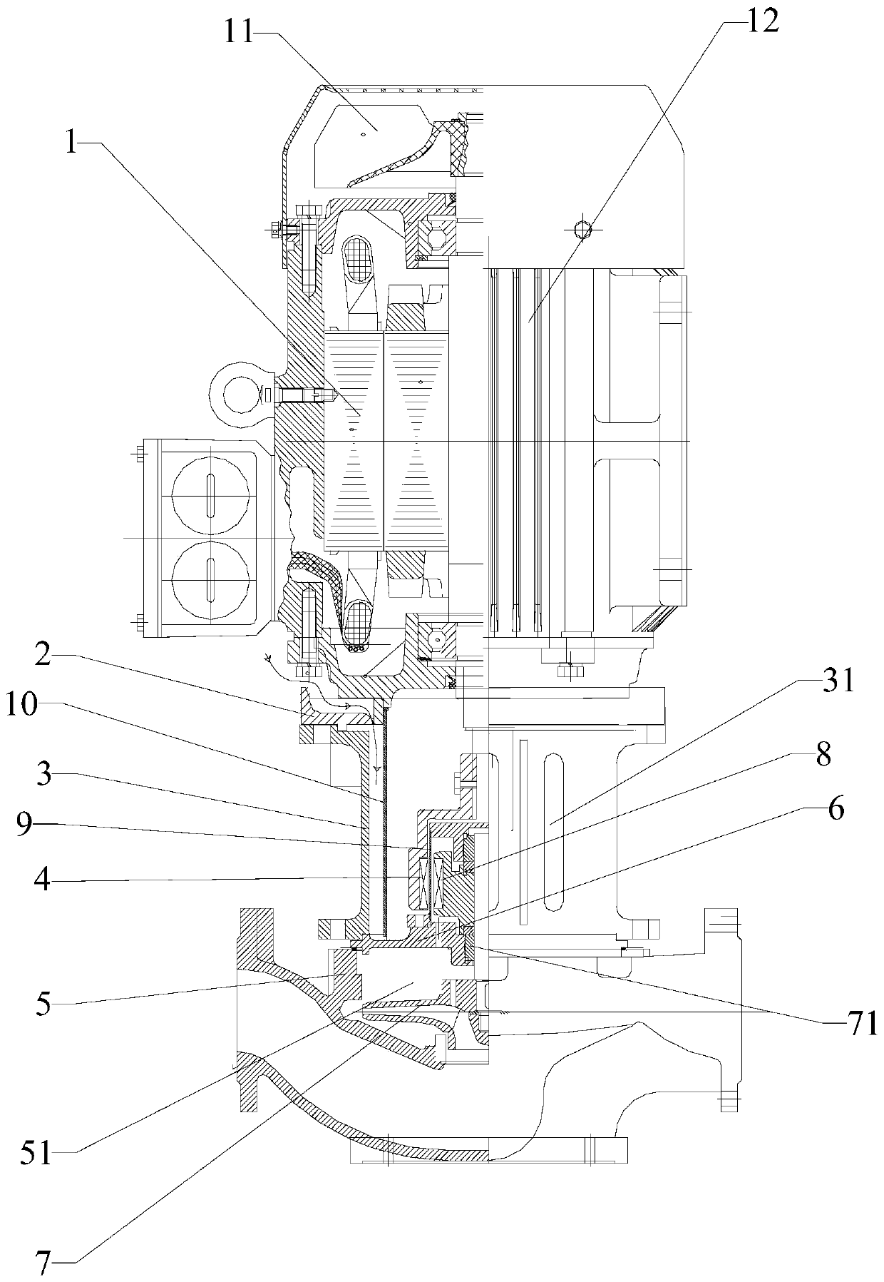
[0042]A magnetic pump, comprising a motor 1, an air guide disk 2, a support 3, an outer magnet 4, a spacer 10, a pump body 5, a pump cover 6, an impeller 7, a rotor 8 and a spacer 9; the outer magnet 4 Connected to the shaft end of the motor 1, the pump cover 6 is sealingly connected with the pump body 5 to form a pump chamber 51, the pump cover 6 is pierced with a rotating shaft 71, and the impeller 7 is connected to the shaft 71 located in the pump chamber 51 At one end, the rotor 8 is connected to the rotating shaft 71, the rotor 8 is located outside the pump chamber 51, and the spacer sleeve 9 is connected to the side of the pump cover 6 away from the pump chamber 51, so that the rotor 8 is sealed and isolated between the pump cover 6 and the pump chamber 51. In the sealed cavity formed by the isolation sleeve 9, the outer magnet 4 is suspended and sleeved outside the isolation sleeve 9; the bracket 3 is suspended and sleeved outside the outer magnet 4, and one end of the b...


PUM


Abstract

The invention relates to a magnetic pump. The magnetic pump comprises a motor, an air guide disc, a bracket, an outer magnet, a pump body, a pump cover, an impeller, a rotor and an isolation sleeve, wherein the air guide disc is additionally arranged between the support and a motor end cover, and a flange on an outer edge of the air guide disc plays a role in air guide, so that airflow generated by a fan at a motor shaft end is guided to an inner side of the flange through a surface of the motor outer cover and guided into the support through a gap between the air guide disc and the motor endcover; air moisture between the outer magnet and the isolation sleeve is prevented from being frozen at low temperature or excessively high in temperature, the outer magnet and the rotor are blocked in a closed cavity formed by the motor end cover, the isolation sleeve and the pump cover through the isolation sleeve, moisture in external air is prevented from entering the gap between the outer magnet and the isolation sleeve, the situation that the transmission of the magnetic pump is affected due to a fact that the moisture is frozen is avoided, the direct butt joint of the support and the motor can be avoided through the air guide disc, and the situation that the normal operation of the magnetic pump is affected due to the fact that excessively heat or excessively cold temperature of thetransmission medium is directly transmitted to the motor is avoided.

Description

technical field [0001] The invention relates to the technical field of liquid pump structures, in particular to a magnetic pump. Background technique [0002] In the structure of the magnetic drive pump, the transmission shaft of the motor does not need to penetrate the pump casing, but the inner magnetic rotor is driven by the magnetic field through the magnetic field and the thin-walled transmission torque of the isolation sleeve, so the leakage channel of the shaft seal is fundamentally eliminated, and all Complete sealing between the pumped liquid and the motor. [0003] When the transmission medium of the magnetic pump is a high-temperature medium, the high temperature will be transmitted to the motor through the bracket, causing the temperature of the motor to rise, thereby reducing the service life of the motor, and even causing the motor to burn out; [0004] When the transmission medium of the magnetic pump is cryogenic medium (including liquid LNG or liquid nitrog...

Claims


Application Information

Patent Timeline
Patent Type & Authority Applications(China)
IPC IPC(8): F04D29/00F04D29/58F04D7/02F04D7/06F04D13/06
CPCF04D7/02F04D7/06F04D13/0606F04D29/007F04D29/5806F04D29/5886F04D29/5893
Inventor 郑石全
Owner 福建省福安市力德泵业有限公司
Why Eureka
Try Eureka