Driving bevel gear shaft

A technology of bevel gears and axles, which is applied in the fields of application, farming equipment, agricultural machinery and implements, etc., can solve the problems of large transmission power loss, low transmission efficiency, and easy damage to the chain, and achieves simple structure, axial and radial fixation Strong and reliable effect

Inactive Publication Date: 2016-03-23
WEIMA AGRI MACHINERY CO LTD
View PDF0 Cites 0 Cited by
  • Summary
  • Abstract
  • Description
  • Claims
  • Application Information

AI Technical Summary

Problems solved by technology

[0002] Tillers are powered by small diesel engines or gasoline engines, and have the characteristics of light weight, small size, and simple structure. Tillers are widely used in dry land, paddy fields, orchards, etc. in plains, mountains, and hills. They can be pumped with corresponding equipment. , power generation, spraying, spraying and other operations, and can also be towed by a trailer for short-distance transportation. The tiller can be used freely in the field, which is convenient for users to use and store. It saves the trouble that large agricultural machinery cannot enter the mountainous fields. The best choice for the majority of farmers to replace cattle plowing. The power part of the traditional micro tillage machine generally includes the power device and the transmission device. At present, the micro tillage machine travel transmission device adopts transmission mechanisms such as belts and chains, which has low transmission efficiency and low transmission efficiency. The power loss is large, the chain is easily damaged during transmission, and the maintenance is inconvenient, etc.

Method used


Image

  • Driving bevel gear shaft
  • Driving bevel gear shaft

Examples


Embodiment Construction

[0014] The present invention will be further described below in conjunction with the embodiments and drawings.

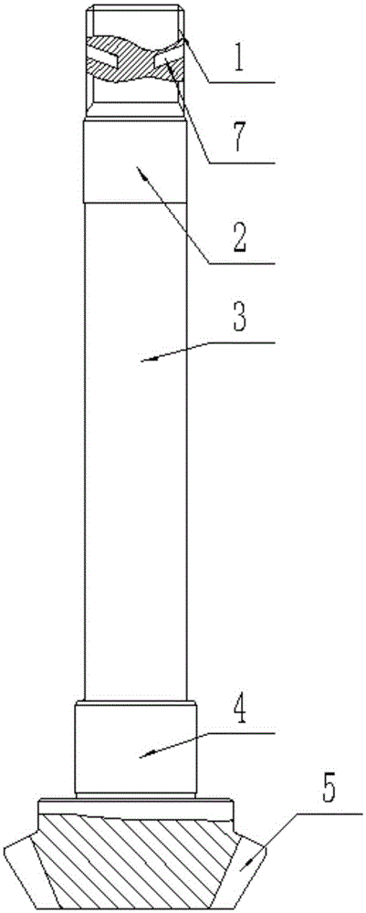
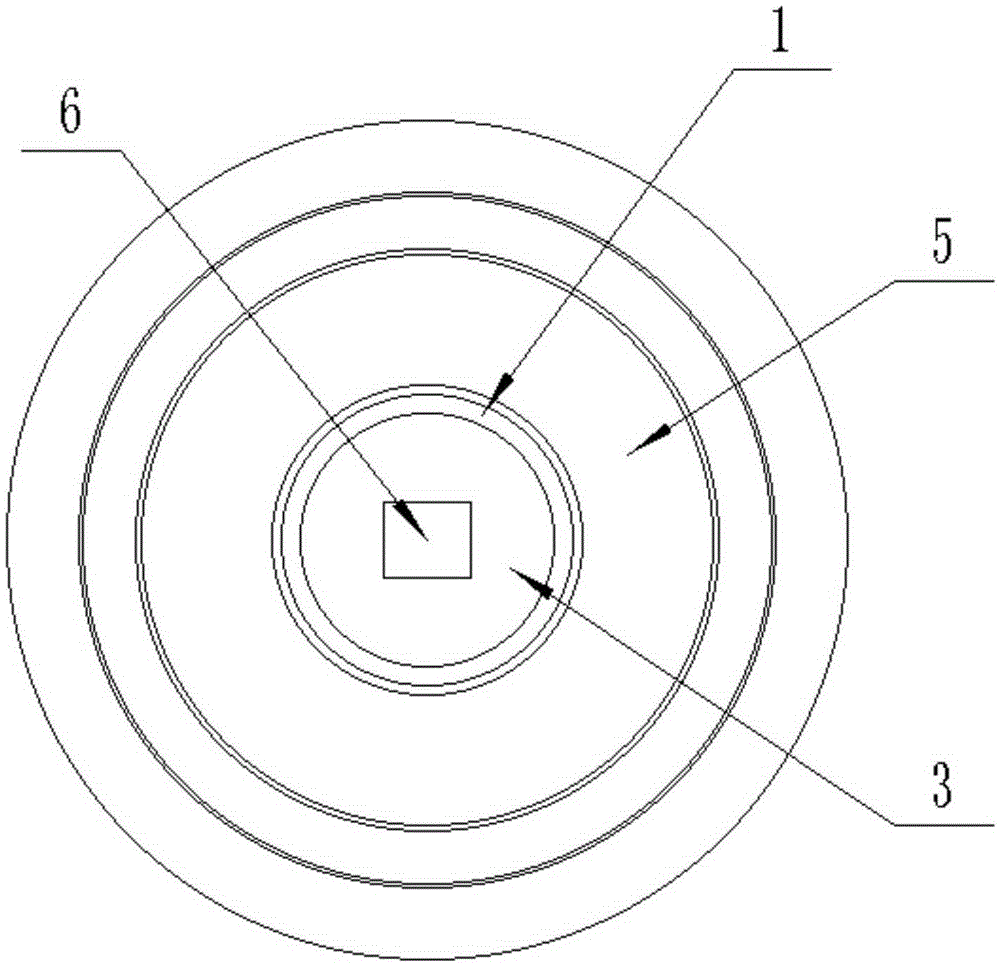
[0015] Such as figure 1 with figure 2 As shown, a transmission bevel gear shaft includes a bevel gear shaft 3 arranged vertically, a bevel gear 5 is provided at the lower end of the bevel gear shaft 3, and the bevel gear shaft 3 and the bevel gear 5 are integrally formed. The upper end of the bevel gear shaft 3 is provided with an external spline 1, and the bevel gear shaft 3 between the bevel gear 5 and the external spline 1 is provided with a first bearing mount 4 and a second bearing mount 2, The first bearing mounting seat 4 is close to the bevel gear 5, the second bearing mounting seat 2 is close to the external spline 1, the shafts of the first bearing mounting seat 4 and the second bearing mounting seat 2 The axial length is the same, the ratio of the axial length of the two to the axial length of the bevel gear shaft 3 is 1:6~1:9, and the diameter of the firs...


PUM


Abstract

The present invention discloses a driving bevel gear shaft. The driving bevel gear shaft comprises a vertically disposed bevel gear shaft. A lower end of the bevel gear shaft is provided with a bevel gear; an upper end of the bevel gear shaft is provided with an external spline; a first bearing mounting seat and a second bearing mounting seat are disposed on the bevel gear shaft between the bevel gear and the external spline; the first bearing mounting seat is close to the bevel gear; and the second bearing mounting seat is close to the external spline. According to the bevel gear shaft disclosed by the present invention, an axial fixing hole and an inclined hole for fixing the bevel gear shaft are disposed on an upper end surface and an upper end of the bevel gear shaft respectively, and when the upper end of the bevel gear shaft is connected to another member, a fixing pin can be inserted into the axial fixing hole and the inclined hole for fixing the bevel gear shaft, so that the bevel gear shaft can be more reliably and securely fixed with the another member in axial and radial directions; additionally, a hole bottom of the inclined hole for fixing the bevel gear shaft is downward inclined, so that sliding of the inserted fixing pin from the hole is effectively avoided. The entire driving bevel gear shaft is simple in structure, and is firm and durable.

Description

Technical field [0001] The invention relates to a shaft, in particular to a transmission bevel gear shaft. Background technique [0002] The micro-tiller is powered by a small diesel engine or gasoline engine, and has the characteristics of light weight, small size, simple structure, etc. The micro-tiller is widely used in plains, mountains, hills, dry land, paddy fields, orchards and other places. It can be pumped with corresponding equipment , Power generation, spraying, spraying, etc., and can also be towed for short-distance transportation. The tiller can be used freely in the field, which is convenient for users to use and store, eliminating the trouble that large agricultural machinery cannot enter mountainous fields. Farmers and consumers are the best choice to replace cattle farming. The power part of traditional tillers generally includes power devices and transmission devices. The current walking transmission devices of tillers use belts, chains and other transmission m...

Claims


Application Information

Patent Timeline
Patent Type & Authority Applications(China)
IPC IPC(8): A01B33/08
CPCA01B33/082
Inventor 严华
Owner WEIMA AGRI MACHINERY CO LTD
Why Eureka
Try Eureka