
A variable flow pulse hydraulic fracturing method

A hydraulic fracturing and variable flow technology, applied in the fields of fluid production, earthwork drilling, wellbore/well components, etc., can solve the problem of prolonged operation time, construction technology and parameter design method of pulse injection flow rate, and equipment reliability. It can reduce the time cost, improve the fracturing effect, and save the operation time.

Active Publication Date: 2021-04-16
YANSHAN UNIV
View PDF5 Cites 0 Cited by
  • Summary
  • Abstract
  • Description
  • Claims
  • Application Information

AI Technical Summary

Problems solved by technology

However, in order to achieve the purpose of fatigue rock breaking, it is often necessary to go through multiple cycles and prolong the working time
Moreover, in order to generate variable loads at the bottom of the well, additional auxiliary equipment is required to generate pulsating flow or pressure (ZL201810725110.2), which may involve issues such as equipment reliability and complex operating processes
[0004] In summary, it can be seen that the effective and simple hydraulic fracturing technology for difficult-to-fracture reservoirs has extremely high economic effects and application prospects. However, so far, there have been no reports on the construction technology and parameter design method of pulse injection flow.

Method used


Image

  • A variable flow pulse hydraulic fracturing method
  • A variable flow pulse hydraulic fracturing method
  • A variable flow pulse hydraulic fracturing method

Examples


specific Embodiment 1

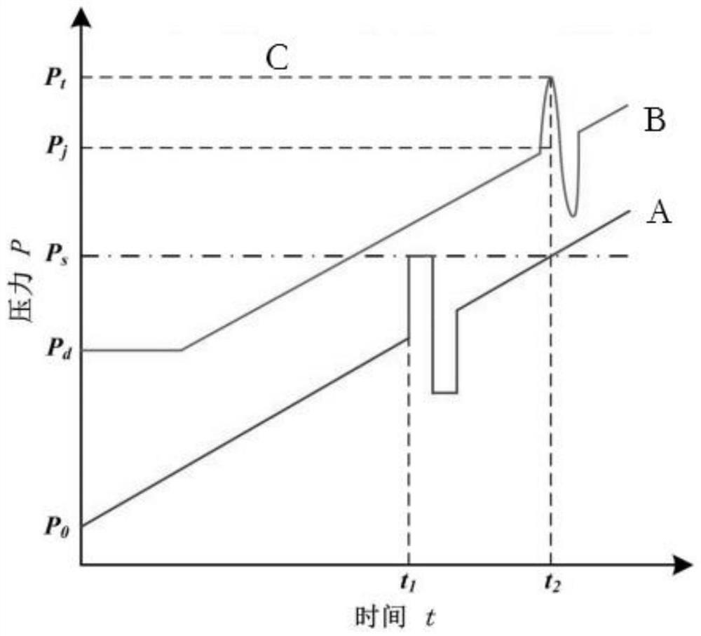
[0063] Step 1. The fracturing operation reservoir is located 2000m underground, the fracture strength of the rock is 110MPa, and the safety limit pressure of the wellhead equipment is P S is 75MPa. After the fracturing construction site equipment and personnel are ready, the conventional constant injection flow rate Q 0 3m 3 / min for fracturing operation, injection time t 2 After 13.6217s, the wellhead pressure is close to the ultimate pressure, while the bottom hole pressure is only 98.1MPa, which is far less than the fracture strength of the rock, and the operation cannot be continued. At this time, stop the injection, confirm the stop injection time, and restore the wellhead pressure to the level before the injection state.

[0064] Step 2. According to the property parameters of the pipe string and fracturing fluid, the propagation speed C of the pressure wave is calculated as 969 m / s by the following formula.

[0065]

[0066] In the formula: E is the elastic modul...


PUM


Abstract

The invention provides a variable-flow pulse hydraulic fracturing process, which relates to the field of hydraulic fracturing stimulation of oil and gas wells. The following steps are sequentially included: S1, injecting fracturing fluid at a constant flow rate and recording the change of wellhead pressure, and stopping the injection when the wellhead pressure is close to the safe pressure; S2, calculating the propagation velocity of the pressure wave in the liquid; S3, calculating the flow adjustment time; S4. Find out the wellhead pressure corresponding to the injection stop time and the flow adjustment time according to the recorded wellhead pressure over time, and calculate the corresponding pressure difference between the two times, and estimate the flow adjustment amplitude according to the pressure difference. S5. Redesign the pulse-changing flow injection scheme according to the above calculation results, and perform the fracturing operation again. The invention utilizes the pulse pressure wave generated by the sudden pulse injection flow to carry out fracturing operation on the reservoir layer, which can effectively perform fracturing operation on the reservoir layer with poor physical properties, low porosity and high fracture strength, and improves the fracturing effect.

Description

technical field [0001] The invention relates to the field of hydraulic fracturing stimulation measures for oil and gas wells, in particular to a variable flow pulse hydraulic fracturing process. Background technique [0002] In the process of hydraulic fracturing construction, for reservoirs with poor physical properties, low porosity and high fracture strength, higher construction pressure is often required, and considering the construction safety of equipment and personnel, it is often necessary to set a safe limit pressure. In the process of fracturing, it is often encountered that the wellhead pressure is close to the ultimate pressure, but the reservoir has not yet ruptured. For safety reasons, conventional countermeasures need to stop the continuous injection, re-acidify or adjust the construction process, which greatly delays the operation period, increases input costs, and causes huge economic losses. [0003] Change the constant flow injection mode in the conventio...

Claims


Application Information

Patent Timeline
Patent Type & Authority Patents(China)
IPC IPC(8): E21B43/26
CPCE21B43/26
Inventor 董世民朱葛李伟成王宏博潘子卜
Owner YANSHAN UNIV
Learn More