High-speed computer plate cutting saw, control system and machining method
A computerized panel saw, high-speed technology, applied in the control system and processing, high-speed computerized panel saw field, can solve the problems of large floor space, inability to complete one-time sawing of panels, and high equipment costs, and achieve simplified structure and reliable action. , the effect of reducing costs
- Summary
- Abstract
- Description
- Claims
- Application Information
AI Technical Summary
Problems solved by technology
Method used
Image
Examples
Embodiment 1
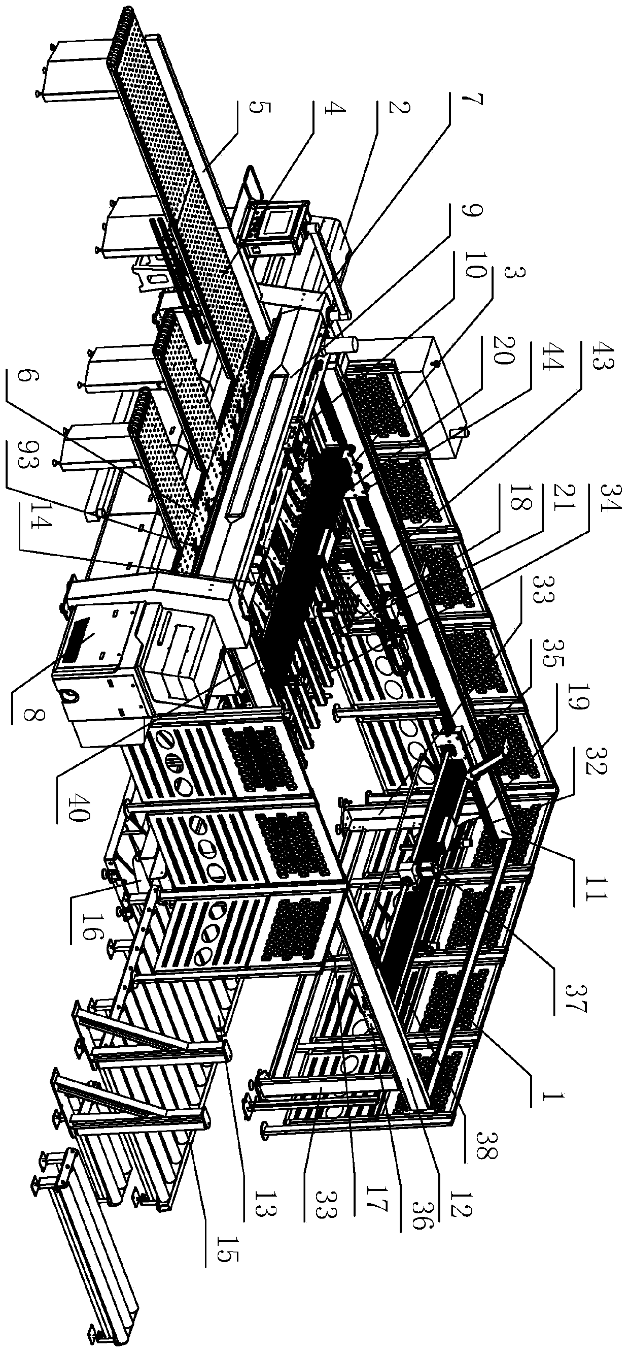
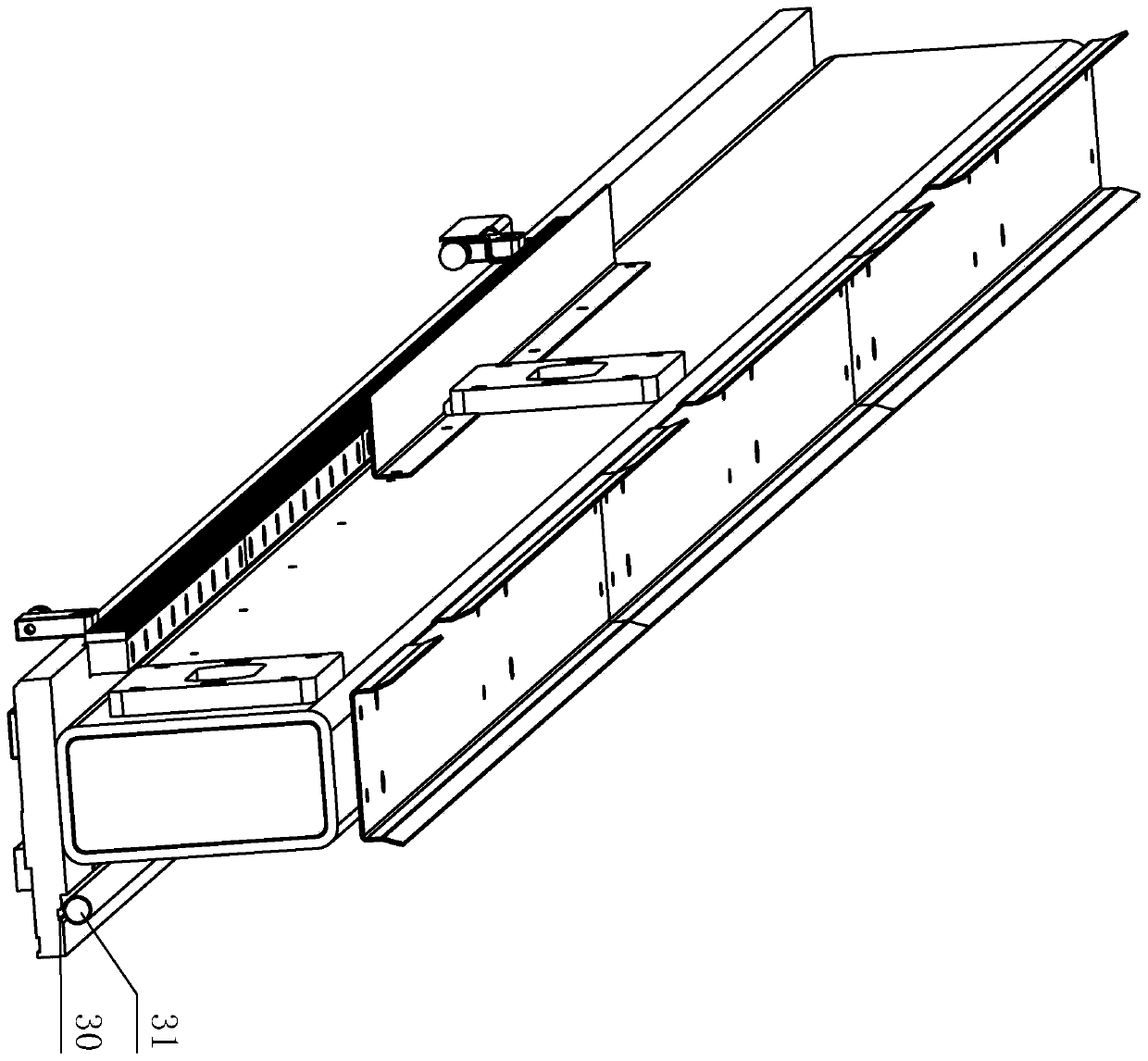
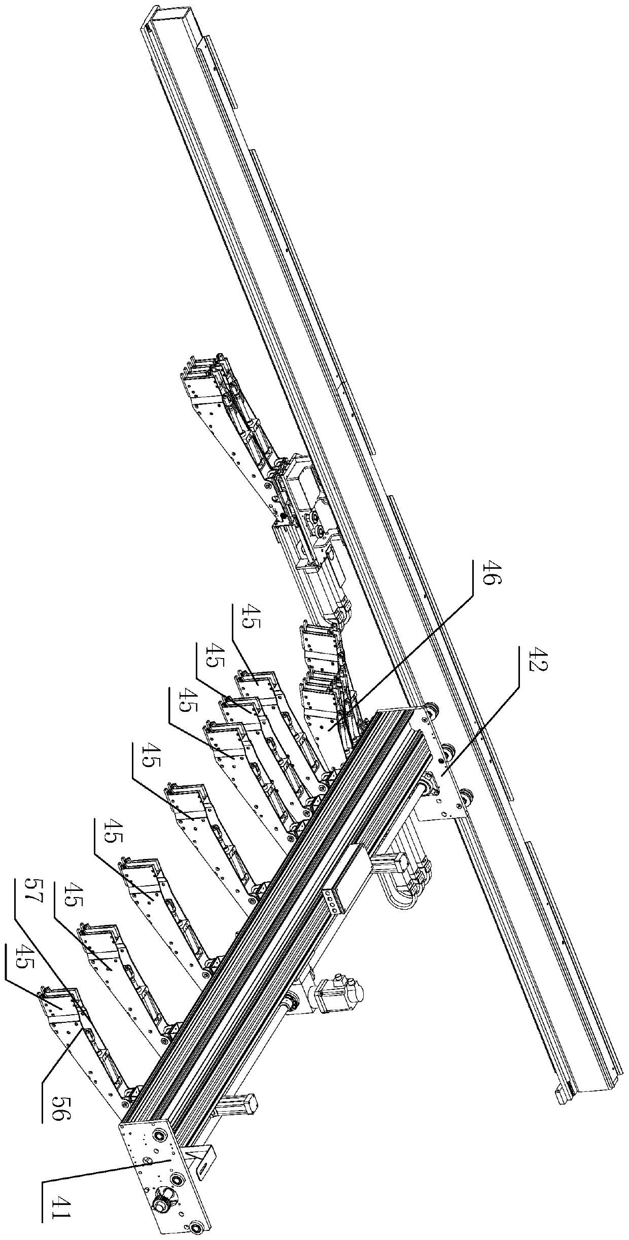
[0226] Please refer to Figure 1 to Figure 9 As shown, it shows the specific structure of the embodiment of the present invention.
[0227] First of all, it should be noted that in the following descriptions, some terms "upper", "lower", "front", "rear", "left", "right", "vertical", "horizontal", "top" , "bottom", "inner", "outer" and other indicated orientations or positional relationships are based on the orientations or positional relationships shown in the drawings, and are only for the convenience of describing the technical solution of the present invention and simplifying the description, rather than indicating or implying the Indicates that a device or element must have a particular orientation or be constructed and operated in a particular orientation and, therefore, should not be construed as limiting the invention.
[0228] Such as Figure 1 to Figure 3 As shown, a high-speed computerized panel saw includes a main frame 1, a machine body 2 installed on the main fr...
Embodiment 2
[0279] Such as Figure 10 As shown, a control system of a high-speed computerized panel saw includes a man-machine exchange control unit, a programmable controller (PLC) connected to the man-machine exchange control unit through Ethernet for two-way control, and the data connected to the programmable controller Bus, two-way control The feeding device control unit, the pushing device control unit, the front trimming device control unit, the main work clamp feeding device control unit, the auxiliary work clamp feeding device control unit, the synchronization device control unit are connected in parallel to the data bus , Side alignment device control unit, pressing device control unit, cutting device control unit.
[0280] The man-machine exchange control unit includes an industrial computer, a mouse and keyboard connected to the industrial computer for one-way control, a factory LAN connected to the industrial computer for two-way control, and a mouse and keyboard for one-way c...
Embodiment 3
[0335] The working method of high-speed computerized panel saw, including Figure 15 to Figure 20 All steps shown.
[0336] Such as Figure 15 As shown, first perform the following steps in sequence:
[0337] boot system initialization;
[0338] Return to the origin, including the cutting device, the main worker's pinch feeding device, the auxiliary worker's pinch feeding device, and the pushing device move to the set origin position; after the origin reset, input the processing pattern;
[0339] Input the processing pattern; manually edit the processing pattern or automatically import the processing pattern, select the processing pattern, click download data, download the processing pattern to the PLC, and complete the input processing pattern;
[0340] After inputting the processing pattern, do you want to execute the post-loading and board program?
[0341] If not, start the front loading and board program; start the front loading and board program, then only manually p...
PUM
 Abstract
Description
Claims
Application Information
 - R&D
- Intellectual Property
- Life Sciences
- Materials
- Tech Scout
- Unparalleled Data Quality
- Higher Quality Content
- 60% Fewer Hallucinations
Browse by: Latest US Patents, China's latest patents, Technical Efficacy Thesaurus, Application Domain, Technology Topic, Popular Technical Reports.
© 2025 PatSnap. All rights reserved.Legal|Privacy policy|Modern Slavery Act Transparency Statement|Sitemap|About US| Contact US: help@patsnap.com


