Die-cutting automatic rubber repairing device

A driving device and automatic technology, which is applied in the direction of grinding/polishing safety devices, grinding machines, metal processing equipment, etc., can solve the problems of affecting devices, taking up a lot of labor time, and loud noise, and achieve the effect of reducing noise pollution

Active Publication Date: 2020-08-18
扬州伟鹏机械有限公司
View PDF9 Cites 0 Cited by
  • Summary
  • Abstract
  • Description
  • Claims
  • Application Information

AI Technical Summary

Problems solved by technology

[0005] When the die-cutting glue repairing device with this structure is used, the rubber pad is polished to generate a lot of dust, which accumulates on the grinding wheel and affects the grinding effect of the device. Although this problem can be solved by cleaning in time, the operation is troublesome and labor-intensive More time; in addition, when the device is in operation, the noise is relatively large

Method used


Image

  • Die-cutting automatic rubber repairing device
  • Die-cutting automatic rubber repairing device
  • Die-cutting automatic rubber repairing device

Examples


Embodiment 1

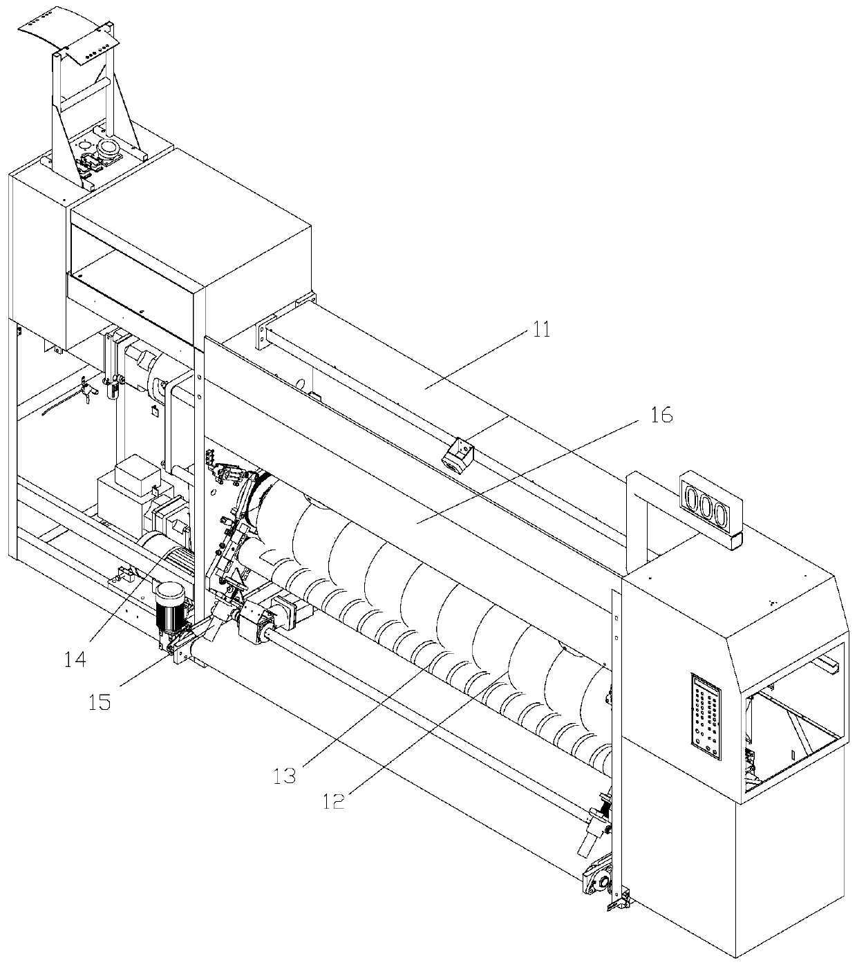
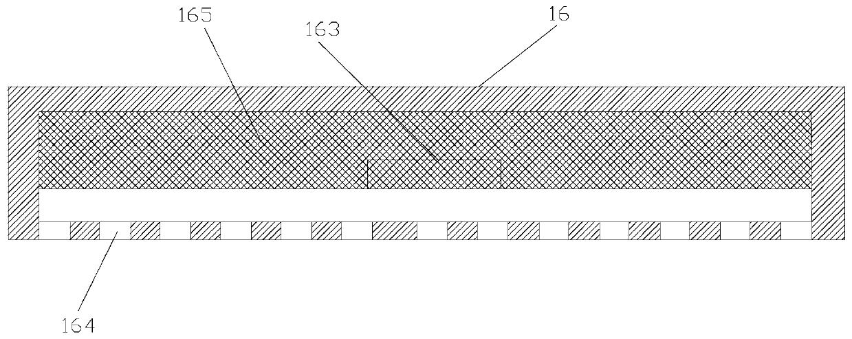
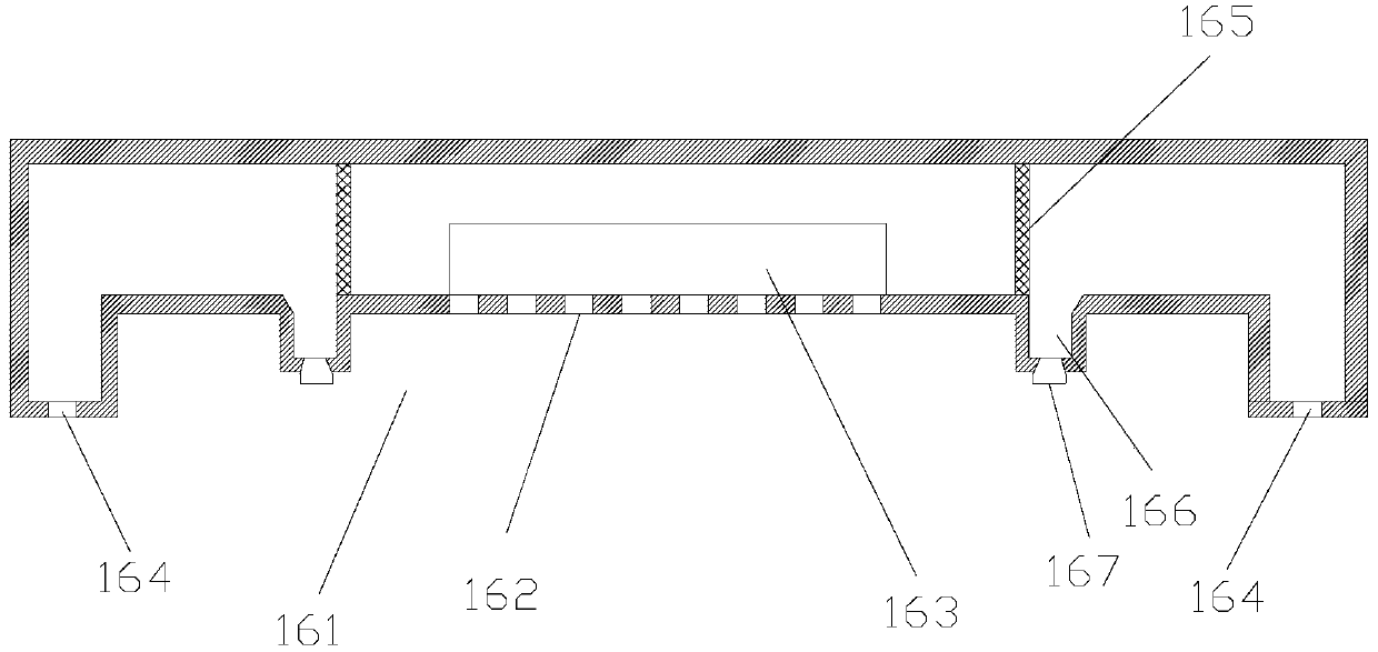
[0025] Embodiment 1, the present invention provides a die-cutting automatic glue repairing device, see Figure 1-Figure 3 , including a housing 11, in which a rubber pad wheel 12, a grinding wheel 13, a driving device and a lift are installed, the rubber pad wheel is connected with the driving device, the grinding wheel is connected with the lift, the Inside the casing, a dust box is also installed above the rubber pad wheel. The dust box includes a box body 16. A groove 161 is arranged at the bottom of the box body. A first hole 162 communicated inside the body, a plurality of the first holes form air outlet holes, the air outlet holes are facing the grinding wheel, and a fan 163 is installed in the box at the positions of the plurality of first holes, The bottom end of the box body is provided with a plurality of second holes 164 on both sides of the groove, which communicate with the inside of the box body. Generally, a plurality of second holes are arranged laterally, and ...

Embodiment 2

[0029] Example 2, on the basis of Example 1, the applicant also made the following design, see Figure 4 , the filter device is a filter screen, and the filter screen is preferably an elastic filter screen, preferably made of non-magnetic material, and the filter screen is laterally fixed with a magnetic elastic sheet 18 in the middle position close to the side of the fan. The magnetic elastic sheet described here It means that the shrapnel contains magnetic material, a spring 19 is longitudinally installed below the magnetic shrapnel, and a magnet block 20 is fixed on the top of the spring, that is, a block made of magnets, and the magnet block and the magnetic shrapnel are spaced apart , In this structure, when the device is in use, the operation of the fan generates vibration, which makes the spring and the magnetic shrapnel vibrate. When the spring moves up and the magnetic shrapnel moves down, the magnet block has an enhanced adsorption force on the magnetic shrapnel, ther...

Embodiment 3

[0031] Example 3, on the basis of Example 1 or Example 2, the applicant also made the following design, see Figure 5 , the top of the dust collecting tank is inclined and fixed with a rubber sheet 168 on the side away from the filter device, and the distance from the top end of the rubber sheet to the filter screen is greater than the position from the bottom end to the filter screen; The bottom of the rubber sheet is provided with a third hole 168-1 horizontally, and the third hole can be set as one or a group (that is, a row), and the side away from the dust collecting tank is provided with a plurality of or Multiple groups (that is, multiple rows) of fourth holes 168-2, one or one group (that is, one row) of fifth holes 168-3 are provided on the side close to the dust collecting tank, and a plurality of the fourth holes are provided Connected with the fifth hole, and a plurality of the fourth holes and the fifth holes are arranged obliquely, and the inclination direction i...


PUM


Abstract

The invention relates to a die-cutting automatic rubber repairing device. The die-cutting automatic rubber repairing device comprises a shell body, wherein rubber cushion wheels, grinding wheels, a driving device and a lifting machine are installed in the shell body; the rubber cushion wheels are connected with the driving device; the grinding wheels are connected with the lifting machine; and a dust removal box is installed at the position, above the rubber cushion wheels, in the shell body. The dust removal box comprises a box body, wherein a groove is formed in the bottom of the box body, aplurality of first holes communicating with the interior of the box body are formed in the groove, and the multiple first holes form air outlets; the air outlets are right opposite to the grinding wheels, a draught fan is installed at the position, located at the multiple first holes, in the box body, and a plurality of second holes communicating with the interior of the box body are formed in the positions, located on the two sides of the groove, of the bottom end of the box body; the multiple second holes form air inlets, and the first holes and the second holes are sound eliminating holes;and filtering devices are installed at the positions, located on the two sides of the draught fan, in the box body, dust collecting grooves are formed in the sides, away from the draught fan, of thebottoms of the filtering devices, and dust exhausting structures are arranged at the bottoms of the dust collecting grooves. According to the die-cutting automatic rubber repairing device, it is not easy for dust to gather on the grinding wheels and affect the grinding effect of the device, and the noise pollution during the operation of the device is reduced.

Description

[0001] The original application number of this divisional application is 201811518481.X, the application date is December 12, 2018, and the name of the invention is "an automatic glue repairing device for die cutting". technical field [0002] The invention relates to the technical field of die-cutting and glue-repairing of cardboard, in particular to an automatic glue-repairing device for die-cutting. Background technique [0003] In the process of cardboard die-cutting, in order to reduce the wear of the tool, the rubber pad is often used, and in order to improve the die-cutting effect, the tool should be in full contact with the rubber pad when cutting the cardboard. Therefore, the rubber pad will be used by the tool. The cutting produces scratches, which will affect the die-cutting effect when die-cutting again. [0004] To this end, people have designed a repairing device to fix the rubber pad to be ground on the rubber pad wheel, the motor drives the rubber pad wheel t...

Claims


Application Information

Patent Timeline
Patent Type & Authority Applications(China)
IPC IPC(8): B24B55/06B24B55/00B24B19/22
CPCB24B19/22B24B55/00B24B55/06
Inventor 萧志明杨淑敏
Owner 扬州伟鹏机械有限公司
Why Eureka
Try Eureka