O-ring continuous supply device

A technology of O-shaped sealing ring and supply device, which is applied in assembly machines, metal processing equipment, metal processing, etc., and can solve problems such as deformation, only women with slender fingers are competent, and operators' fingers are worn out, etc.

Active Publication Date: 2021-09-10
山东金润德新材料科技股份有限公司
View PDF0 Cites 0 Cited by
  • Summary
  • Abstract
  • Description
  • Claims
  • Application Information

AI Technical Summary

Problems solved by technology

However, the seemingly simple manual operation of filling the O-ring into the annular groove has taken up a lot of labor. When you have been engaged in the filling of the sealing ring for a long time, you have to repeatedly insert your fingers into the pipe every day. Occupational diseases that will cause the operator's fingers to be worn, scratched, injured or even deformed
Especially when filling the sealing ring into the 1 / 2" pipe joint, due to the small diameter of the pipe, generally only women with slender fingers can do it. Even such women can only work intermittently, that is, filling every day For the work of small diameter sealing rings, it is necessary to switch to other work for 3-5 days, and no one can bear the continuous work of filling small diameter sealing rings
[0004] Looking at the current situation of the clean pipe production industry, there is an urgent need for a sealing ring automatic filling machine with continuous supply of sealing rings to solve the problem of a large amount of labor force, reduce the labor intensity of workers, and reduce the injury to workers

Method used


Image

  • O-ring continuous supply device
  • O-ring continuous supply device
  • O-ring continuous supply device

Examples


Embodiment Construction

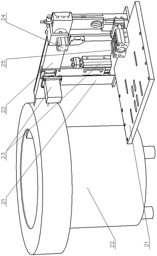
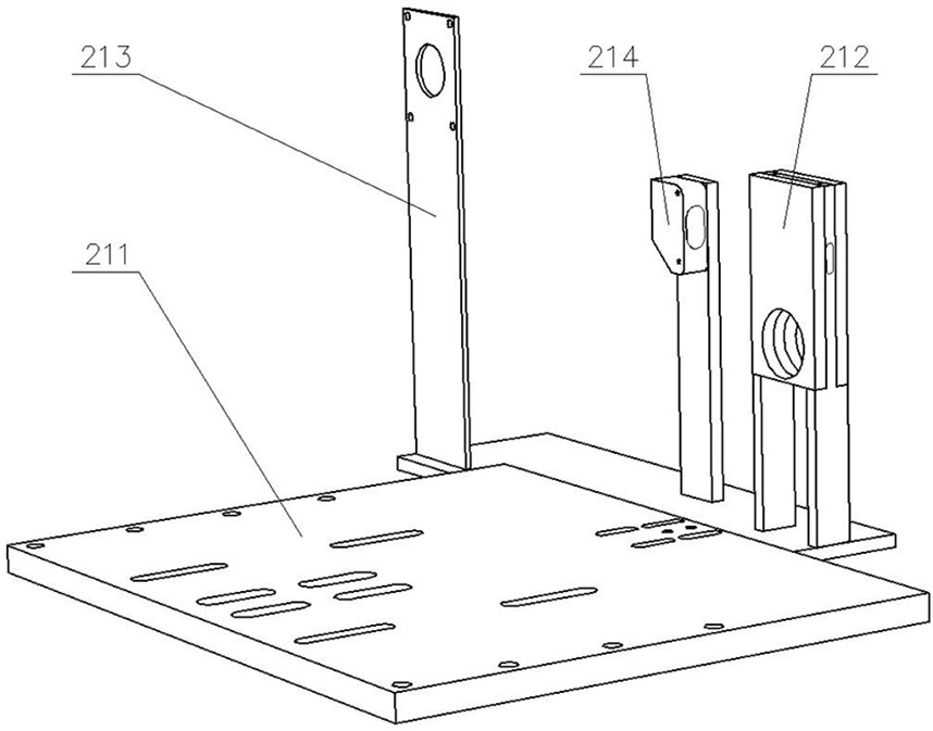
[0023] 2. O-ring continuous supply device 21, supply rack 211, partition 212, vertical channel 213, camera leg 214, photoelectric switch 22, feeding device 221, feeding tray 222, transverse channel 223, compressed air connector 224 , window 23, sorting device 231, sorting cylinder 232, sorting plate 233, camera 24, clamping cylinder 241, clamping cylinder body 242, clamping rod 243, pressure plate 25, bracket cylinder 251, bracket cylinder body 252, bracket bar 253, supporting plate.

[0024] exist Figure 1-Figure 7 In the shown embodiment: the dividing plate 211 arranged horizontally in the supply rack of the O-ring continuous supply device 2 is in the shape of a rectangular flat plate, and the vertical channel 212 in the shape of a rectangular flat plate is along the center of the section perpendicular to the length direction along the vertical channel 212. The length direction is provided with a through hole with a rectangular cross-section, and the long side of the recta...


PUM


Abstract

The invention provides a continuous supply device for O-shaped sealing rings, which is characterized in that: the vertical channel is fixed in the middle of the short side of the partition, one end of the short side of the partition is provided with a camera leg, and the other leg between the vertical channel is equipped with Photoelectric switch; the outlet of the feeding tray is equipped with a transverse channel, and the rectangular cross-section through hole at the other end of the transverse channel is aligned with the rectangular cross-sectional through hole of the vertical channel; the camera installed on the camera leg is aligned and set on the transverse channel plate The sorting plate of the sorting cylinder installed on the transverse channel is aligned with the rectangular cross-section through hole in the middle of the transverse channel; the air outlet of the compressed air joint installed above the end of the transverse channel away from the feeding tray is aligned with the end of the transverse channel The rectangular cross-section through hole at the top, the pressure plate of the clamping cylinder close to the compressed air joint is aligned with the round hole on the end plate of the transverse channel; the plane of the supporting plate of the bracket cylinder installed on the partition is aligned with the lower end of the vertical channel . The invention can replace manual work and has a high degree of automation.

Description

technical field [0001] The invention provides an O-shaped sealing ring continuous supply device, which belongs to a clean pipe joint sealing ring filling machine and has a specific function, and is mainly used for filling the O-shaped sealing ring into the ring groove of the clean pipe. Background technique [0002] With the development of society and the improvement of people's living standards, the tap water pipes made of PVC materials can no longer meet people's pursuit of quality and healthy living needs, while a clean pipe made of stainless steel materials has quietly emerged and has been rapidly developed and developed. Promote apps. [0003] The drinking water pipe network in the building must be inseparable from various pipe joints, and the connection between the pipe joints and the pipes must be sealed. For this reason, an annular groove is generally arranged on the inner wall of each nozzle of the pipe joint, an O-shaped sealing ring is filled in the annular groov...

Claims


Application Information

Patent Timeline
Patent Type & Authority Patents(China)
IPC IPC(8): B23P21/00B23P19/00
CPCB23P19/001B23P19/002B23P21/004
Inventor 李家泉王珅盖波陈大鹏
Owner 山东金润德新材料科技股份有限公司
Why Eureka
Try Eureka