Medical foot massage and stasis dissipation rehabilitation equipment
A rehabilitation equipment and medical technology, applied in the direction of roller massage, kneading massage equipment, massage auxiliary products, etc., can solve the problems of easy soreness of hands, low massage efficiency, inconsistent massage intensity, etc., so as to avoid sore hands and massage. High efficiency and consistent massage force
- Summary
- Abstract
- Description
- Claims
- Application Information
AI Technical Summary
Problems solved by technology
Method used
Image
Examples
Embodiment 1
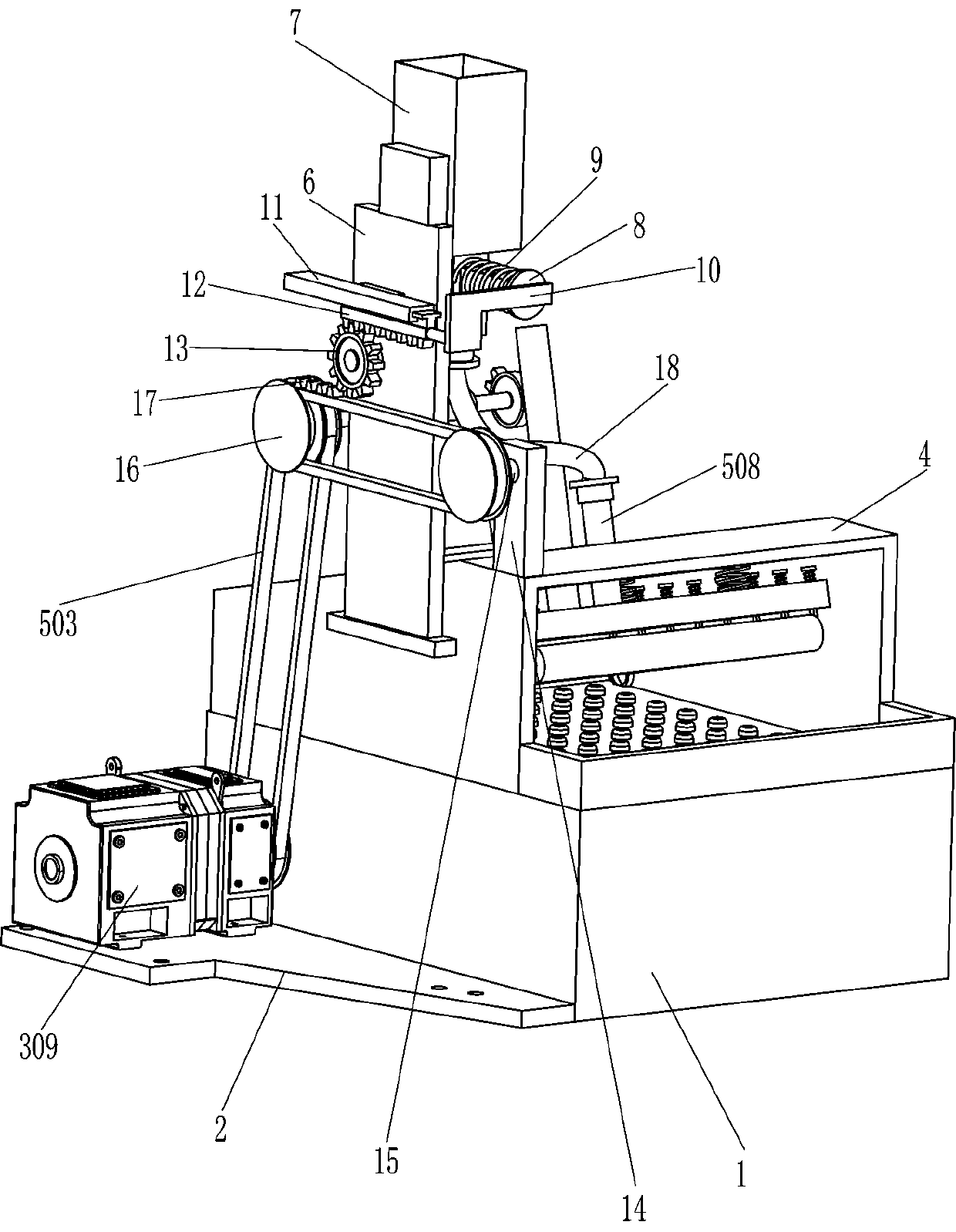
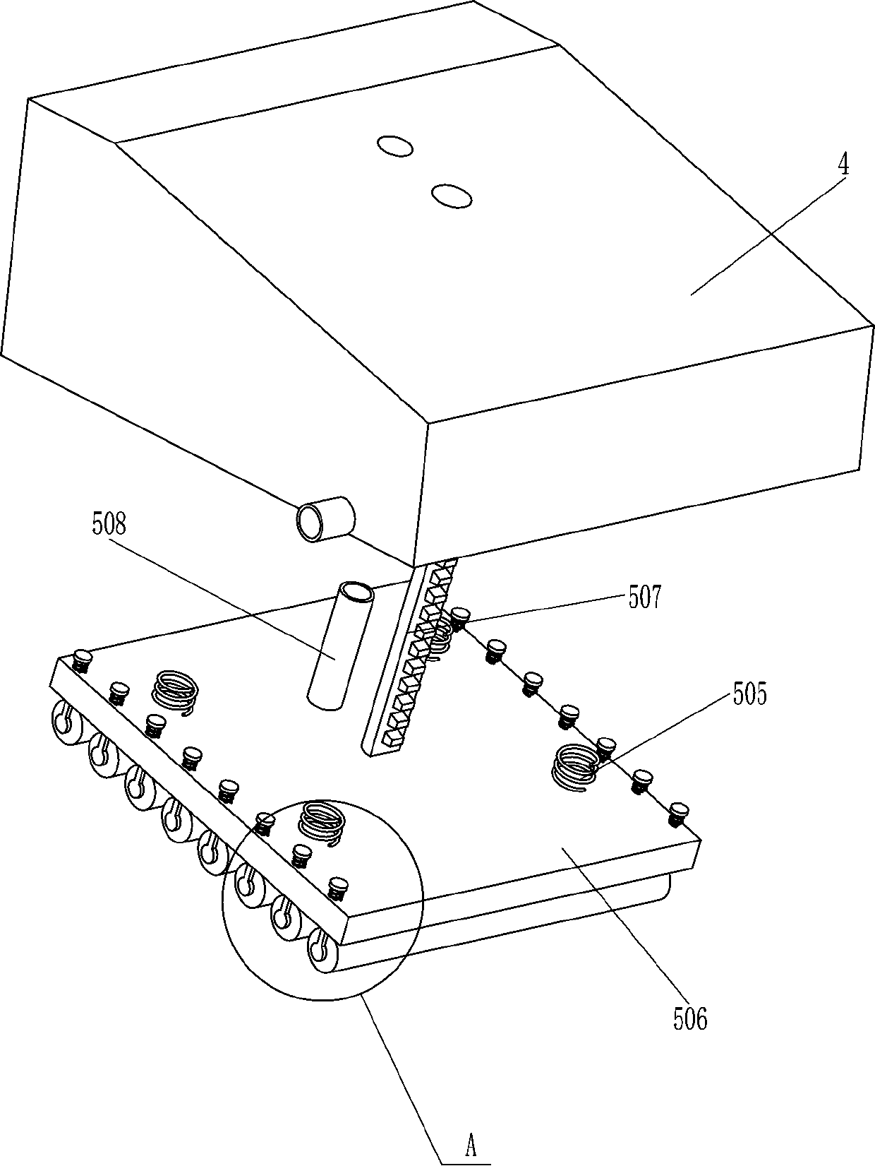
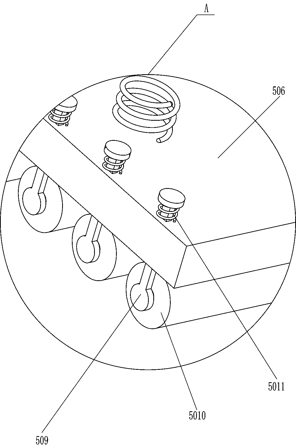
[0023] see Figure 1-Figure 5 , a medical foot massage and silt recovery equipment, including a frame body 1, a mounting plate 2, a massage mechanism 3, a casing 4 and a pressing mechanism 5, a casing 4 is fixedly connected to the top and rear side of the frame body 1, and the casing 4 is provided with a pressing mechanism 5, and the lower part of the outer left side of the frame body 1 is fixedly connected with a mounting plate 2, and a massage mechanism 3 is provided between the top rear side of the mounting plate 2 and the frame body 1, and the massage mechanism 3 is also connected with the pressing mechanism 5 Cooperate.
[0024] The massage mechanism 3 includes a placement plate 301, a massage bar 302, a first spring 303, a first rotating shaft 304, a second rotating shaft 305, a sprocket wheel 306, a chain 307, a push plate 308 and a servo motor 309. There is a first rotating shaft 304 rotatably connected between the front middle part, and a second rotating shaft 305 is...
Embodiment 2
[0030] see figure 1 Compared with Embodiment 1, the main difference of this embodiment is that in this embodiment, it also includes a riser 6, a placement frame 7, a perforated stop rod 8, a fourth spring 9, an L-shaped plate 10, a guide rail 11, a second Rack 12, rotating gear 13, support plate 14, rotating shaft 15, second transmission assembly 16, gear block 17 and liquid outlet pipe 18, vertical plate 6 is fixedly connected to the upper front side of the outer left side of the housing 4, and the vertical plate 6. A placement frame 7 is installed on the top of the right side. The bottom end of the placement frame 7 is connected with a liquid outlet pipe 18. The liquid outlet pipe 18 communicates with the interior of the placement frame 7. The tail end of the liquid outlet pipe 18 is connected with the top of the liquid inlet pipe 508. The pipe 18 communicates with the liquid inlet pipe 508, and the lower part of the placement frame 7 is slidably connected with a perforated ...
PUM
 Abstract
Description
Claims
Application Information
 - R&D
- Intellectual Property
- Life Sciences
- Materials
- Tech Scout
- Unparalleled Data Quality
- Higher Quality Content
- 60% Fewer Hallucinations
Browse by: Latest US Patents, China's latest patents, Technical Efficacy Thesaurus, Application Domain, Technology Topic, Popular Technical Reports.
© 2025 PatSnap. All rights reserved.Legal|Privacy policy|Modern Slavery Act Transparency Statement|Sitemap|About US| Contact US: help@patsnap.com


