Eureka AIR delivers breakthrough ideas for toughest innovation challenges, trusted by R&D personnel around the world.

A new energy charging module

A charging module and new energy technology, applied in the direction of electrical components, power electronics modification, synthetic resin layered products, etc., can solve problems such as the impact of ambient temperature charging module life, equipment, loss of functionality, etc.

Active Publication Date: 2021-12-28
YANTAI AUTOMOBILE ENG PROFESSIONAL COLLEGE
View PDF3 Cites 0 Cited by
  • Summary
  • Abstract
  • Description
  • Claims
  • Application Information

AI Technical Summary

Problems solved by technology

[0003] In the current scope of application of new energy charging modules, the more common ones are the charging modules of new energy equipment cabinets and the charging modules of new energy charging piles, and the charging modules usually adopt a drawer structure because they need to be placed inside the equipment. The terminal uses air cooling for heat dissipation, but after a long period of use, due to the accumulation of dust inside the charging module and the continuous rise of the ambient temperature, it will have an impact on the life of the charging module, and in severe cases, it will also affect the equipment using the charging module. cause loss of functionality

Method used


Image

  • A new energy charging module
  • A new energy charging module
  • A new energy charging module

Examples


Embodiment 1

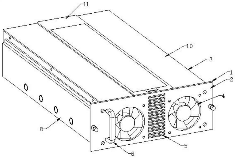
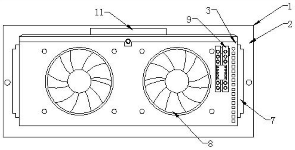
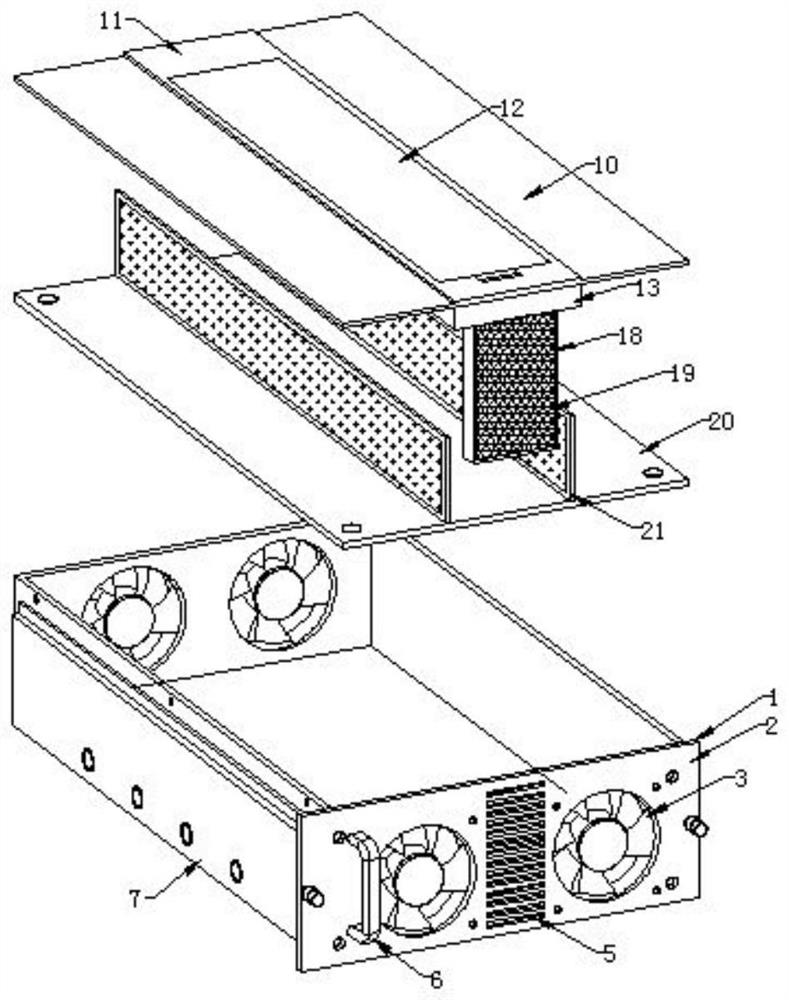
[0025] Such as Figure 1-5 As shown, the present invention provides a new energy charging module, including a charging module main body 1, a front bezel 2 is installed at one end of the charging module main body 1, a box body 3 is installed at one end of the front bezel 2, and a front bezel Front fans 4 are installed on both sides of the surface of the front baffle 2, a cooling vent 5 is installed in the middle of the front baffle 2, a handle 6 is installed on one side of the front fan 4, and side sliding blocks 7 are installed on both sides of the box body 3 A rear fan 8 is installed on both sides of one end surface of the box body 3, a socket 9 is installed on one side of the rear fan 8, a top cover 10 is arranged on the top of the box body 3, and a top sliding block is arranged in the middle of the surface of the top cover 10. 11. A sealing plate 12 is installed at the top middle of the top sliding block 11, an air duct groove 13 is arranged inside the top cover 10, a water...


PUM


Abstract

The invention discloses a new energy charging module, comprising a main body of the charging module, a front baffle is installed at one end of the main body of the charging module, a box is installed at one end of the front baffle, a top cover is arranged on the top of the box, and the top cover The top sliding block in the middle of the surface, the top middle of the top sliding block is installed with a sealing plate, the inside of the top cover is provided with an air duct groove, the middle of the air duct groove is installed with a water storage tank, and the top middle of the water storage tank is installed with a permeable membrane. A water inlet is installed on both sides of the top of the water storage tank, an air outlet is arranged in the middle of the bottom surface of the top cover, an air inlet is arranged on one side of the bottom end of the top cover, and a dust-proof net is installed on the surface of the air inlet. The present invention arranges the air duct groove and the water storage tank inside the top cover, so that the blown wind direction will form a return shape in the air duct groove, and blow to the inside of the main body of the charging module through the surface of the water storage tank, so as to realize the drying of the dry air due to water. The heat absorption effect achieves the effect of cooling the internal air.

Description

technical field [0001] The invention relates to the field of new energy charging, in particular to a new energy charging module. Background technique [0002] The power module is a power supply that can be directly mounted on the printed circuit board, and its characteristic is that it can provide power for application-specific integrated circuits, digital signal processors, microprocessors, memories, field programmable gate arrays and other digital or analog loads . Generally, such modules are called point-of-load power supply systems or point-of-use power supply systems. Due to the many advantages of the modular structure, the module power supply is widely used in communication fields such as switching equipment, access equipment, mobile communication, microwave communication, optical transmission, routers, automotive electronics, aerospace, etc. [0003] In the current scope of application of new energy charging modules, the more common ones are the charging modules of ...

Claims


Application Information

Patent Timeline
Patent Type & Authority Patents(China)
IPC IPC(8): H02M1/00H05K7/20B32B27/02B32B27/40B32B27/30B32B27/12B32B3/06B32B3/08
CPCH02M1/00H05K7/20909H05K7/20918B32B5/02B32B5/26B32B27/12B32B3/06B32B3/08B32B2262/0223B32B2262/0292B32B2250/02B32B2250/20
Inventor 于府平
Owner YANTAI AUTOMOBILE ENG PROFESSIONAL COLLEGE
Why Eureka
Eureka Blog
Learn More