Hot-forming line discharging table double-centering system

The technology of centering system and discharging table is applied in the field of double centering system of discharging table of thermoforming line, which can solve the problems of increasing production cost, unable to meet the production of multi-cavity short blanks, reducing production efficiency, etc., and achieves convenient debugging. , Solve the effect of not being able to produce at the same time and having a simple structure

Pending Publication Date: 2019-07-02
凌云吉恩斯科技有限公司
View PDF0 Cites 0 Cited by
  • Summary
  • Abstract
  • Description
  • Claims
  • Application Information

AI Technical Summary

Problems solved by technology

[0004] The centering system of the discharge table directly determines the product processing range of the thermoforming line. At present, the centering system of the discharge table of the thermoforming line mostly uses a single-row centering finger structure on the discharge table to complete the positioning of a sheet. At least three middle fingers are required in the middle, and a single row of middle fingers cannot meet the production of multi-cavity short blanks such as one mold with three cavities and one mold with four cavities.
[0005] A temporary measure to solve the above problems is to produce multi-cavity products in one mold in separate cavities. One punch only presses two sheets, which not only reduces production efficiency but also increases production costs. Therefore, a fast, accurate and simultaneous positioning of short multi-cavity materials is needed. Sheet thermoforming line discharge table double centering system

Method used


Image

  • Hot-forming line discharging table double-centering system
  • Hot-forming line discharging table double-centering system
  • Hot-forming line discharging table double-centering system

Examples


Embodiment Construction

[0031] The principles and features of the present invention are described below in conjunction with examples, which are only used to explain the present invention and are not intended to limit the scope of the present invention.

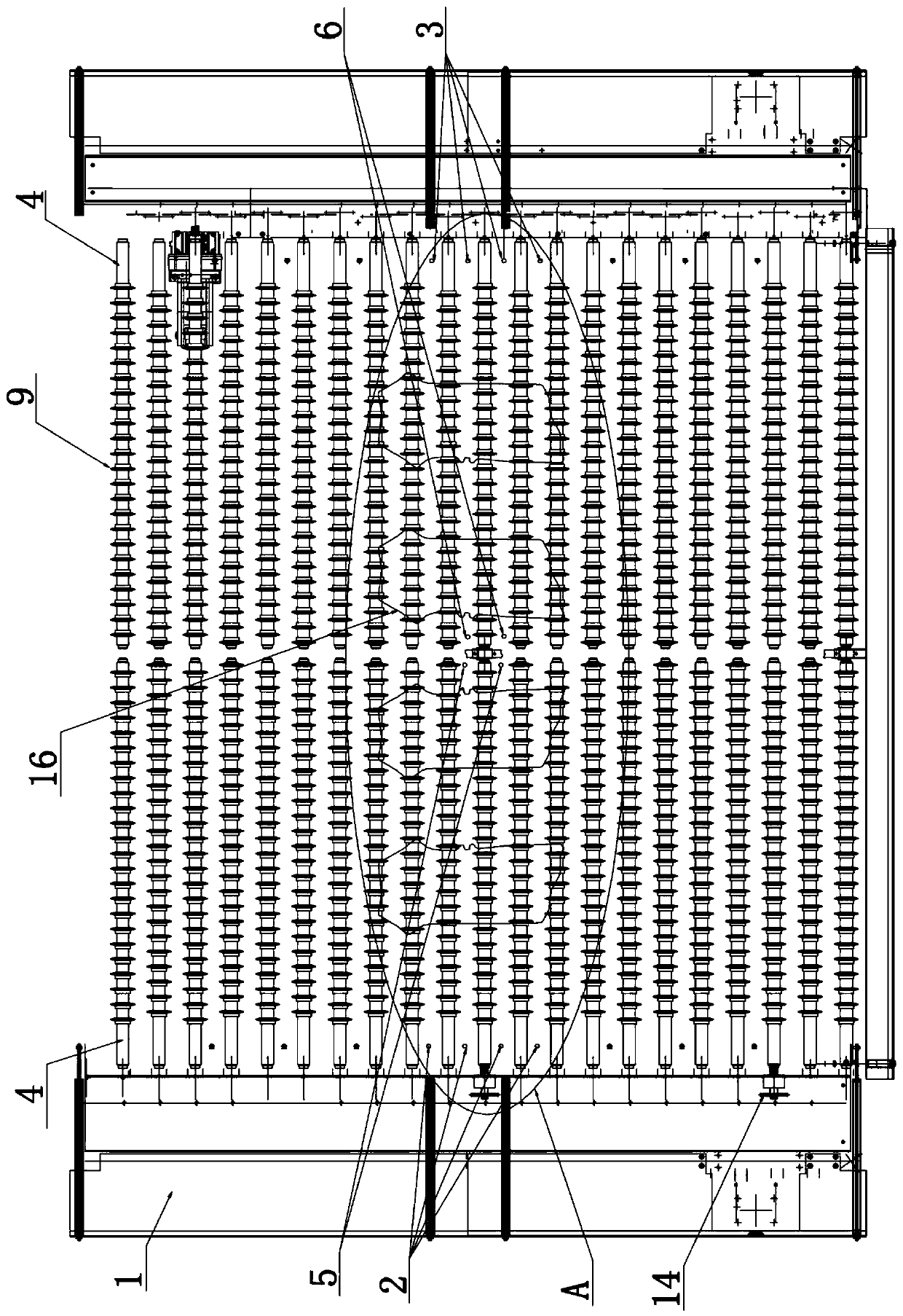
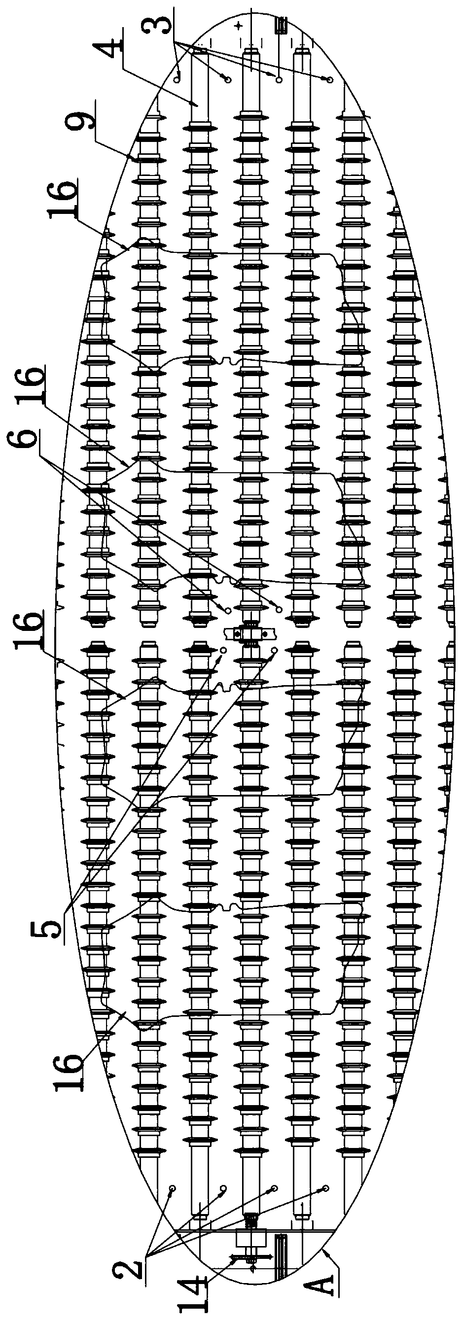
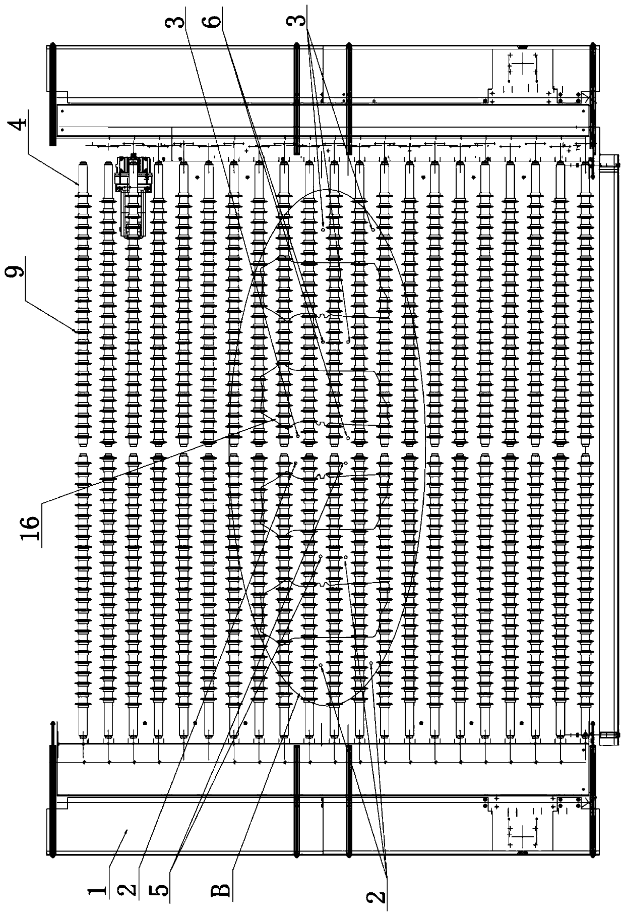
[0032] Such as Figure 1-Figure 8 As shown, a double centering system for a thermoforming line discharge table includes a plurality of first centering fingers 2 and a plurality of second centering fingers 3 arranged on the furnace roller frame 1 of the discharge table, and a plurality of the first centering fingers 3 The middle fingers are arranged in a row on the left side of the furnace roll stand, and a plurality of second middle fingers are arranged in a row on the right side of the furnace roll stand, and the first and second middle fingers are respectively arranged on the Between the above-mentioned conveying rollers, a plurality of conveying rollers 4 arranged in parallel are arranged on the furnace roller frame, and the plurality of conveying...


PUM


Abstract

The invention discloses a hot-forming line discharging table double-centering system. The double-centering system comprises a plurality of first centering fingers and a plurality of second centering fingers, the first centering fingers and the second centering fingers are correspondingly arranged in rows on the left side and the right side of a furnace roller frame, the double-centering system further comprises at least one third centering finger and at least one fourth centering finger arranged between the first centering fingers and the second centering fingers, the third centering finger and the fourth centering finger are correspondingly arranged at the positions, near the left and the right, of the middle part of the furnace roller frame, the first, second, third and fourth centeringfingers are correspondingly arranged between transmission rollers, and the first, second, third and fourth centering fingers move left and right under the action of corresponding driving air cylinders. According to the hot-forming line discharging table double-centering system, the structure is simple, operation is convenient and fast, fast positioning of multiple material sheets can be simultaneously achieved, and the problem that multi-cavity short material sheets can not be simultaneously produced is solved; for material sheet products with complex shapes, more choices of the centering fingers are provided during debugging; the centering fingers are driven by adopting the air cylinder, positions can be adjusted manually after closing air source, and debugging is convenient.

Description

technical field [0001] The invention relates to a double-centering system for a discharge table of a thermoforming line, which belongs to the technical field of thermoforming. Background technique [0002] Thermoforming technology is an emerging technology that originated in the 1980s. It is an innovative and future-oriented part forming technology solution for the automotive industry to reduce the weight of the car body without losing safety in order to achieve the purpose of energy saving and emission reduction. . With the continuous improvement of energy saving and emission reduction requirements, thermoformed parts will be more and more widely used in auto parts. [0003] In the existing production process of thermoformed parts, the blank is heated to about 930°C in the heating furnace, and is quickly transported out of the furnace by the roller table. The sheet is lifted up, and the end picker grabs the material and sends it to the mold for pressing and forming. After...

Claims


Application Information

Patent Timeline
Patent Type & Authority Applications(China)
IPC IPC(8): B65G13/07B65G39/18
CPCB65G13/07B65G39/18
Inventor 安保芹蔡绍龙楚淑云曹兆峰赵彦合杨庆鹏徐永康
Owner 凌云吉恩斯科技有限公司
Why Eureka
Try Eureka