Detection method of chip module

A detection method and technology for chip modules, which are applied in measurement devices, optical testing of flaws/defects, material analysis by optical means, etc., can solve the problems of inability to detect chips, low efficiency, and inconvenient removal of chips, so as to solve the inconvenience The effect of taking out, improving the efficiency of use, and improving the versatility

Inactive Publication Date: 2020-08-14
JIANGSU A KERR BIOLOGICAL RECOGNITION TECH CO LTD
View PDF0 Cites 0 Cited by
  • Summary
  • Abstract
  • Description
  • Claims
  • Application Information

AI Technical Summary

Problems solved by technology

[0004] The technical problem to be solved by the present invention is to provide a detection method for a chip module. The integrated circuit chip detection device solves the problems of inability to detect chips of different specifications, inconvenient removal of chips, and low efficiency.

Method used


Image

  • Detection method of chip module
  • Detection method of chip module
  • Detection method of chip module

Examples


Embodiment 1

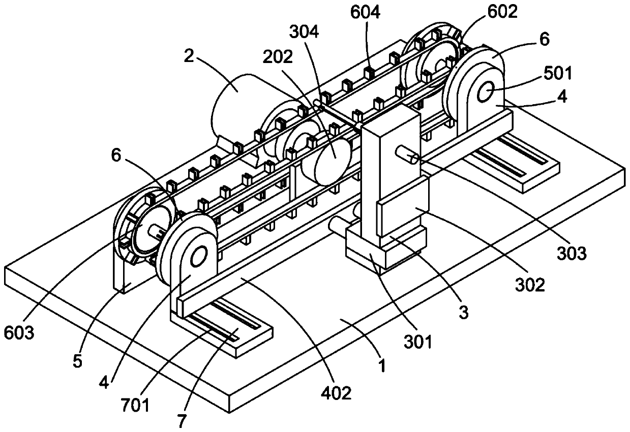
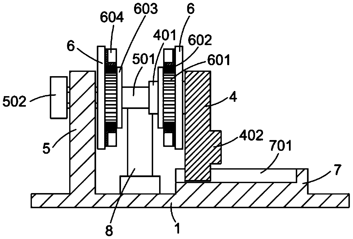
[0036] Embodiment 1: A detection method for a chip module, the detection method is based on a detection device, the detection device includes a base plate 1, a motor 2 installed on the upper surface of the base plate 1, and several fixing devices arranged at intervals on the upper surface of the base plate 1 Plate 5 and several movable plates 4 which are respectively arranged face to face with the fixed plate 5, the motor 2 is installed on the outside of the fixed plate 5 or the movable plate 4, a slide plate 7 is arranged between the base plate 1 and the movable plate 4, the The lower surface of the movable plate 4 is movably mounted on the slide plate 7, so that the movable plate 4 can move towards or away from the fixed plate 5;

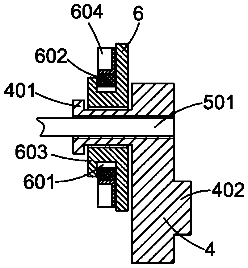
[0037] A limit shaft 501 is connected between the fixed plate 5 and the movable plate 4 which are arranged oppositely. On the side surface of the movable plate 4 close to the fixed plate 5, there is a protruding tube 401 facing the fixed plate 5. T...

Embodiment 2

[0050] Embodiment 2: A detection method of a chip module, the detection method is based on a detection device, the detection device includes a base plate 1, a motor 2 installed on the upper surface of the base plate 1, and several fixing devices arranged at intervals on the upper surface of the base plate 1 Plate 5 and several movable plates 4 which are respectively arranged face to face with the fixed plate 5, the motor 2 is installed on the outside of the fixed plate 5 or the movable plate 4, a slide plate 7 is arranged between the base plate 1 and the movable plate 4, the The lower surface of the movable plate 4 is movably mounted on the slide plate 7, so that the movable plate 4 can move towards or away from the fixed plate 5;

[0051] A limit shaft 501 is connected between the fixed plate 5 and the movable plate 4 which are arranged oppositely. On the side surface of the movable plate 4 close to the fixed plate 5, there is a convex tube 401 facing the fixed plate 5. The ce...


PUM


Abstract

The invention discloses a detection method of a chip module. The device comprises a bottom plate, a motor, a fixed plate and movable plates, wherein a sliding plate is arranged between the bottom plate and the movable plate, the output end of the motor is connected with a rotating shaft, a main gear is mounted at one end of the rotating shaft, an auxiliary gear is mounted on the rotating shaft between the main gear and the motor, the fixed plate and the movable plate are each provided with a rotating disc, the rotating disc is in transmission connection with the auxiliary gear and the main gear through clamping belts, a mounting clamping groove is formed in the outer wall of the clamping belt, the movable plates are connected through a push plate, a mounting frame is arranged on the outerside of the push plate, a first air cylinder and a second air cylinder are mounted on the mounting frame, a CCD camera is connected to a push rod of the second air cylinder, a material returning baseis further mounted on the bottom plate, a third air cylinder is mounted on the material returning base, and a rubber strip is connected to the output end of the third air cylinder. The problems that chips of different specifications cannot be detected, the chips are inconvenient to take out, and the chips cannot be shot accurately are solved.

Description

technical field [0001] The invention relates to a detection method of a chip module and belongs to the technical field of integrated circuit detection. Background technique [0002] Integrated circuit (integrated circuit) is a kind of miniature electronic device or component. It uses a certain process to interconnect the transistors, resistors, capacitors, inductors and other components and wiring required in a circuit, and make them in a small or several small pieces. On a semiconductor wafer or a dielectric substrate, and then packaged in a tube, it becomes a microstructure with the required circuit functions; most of the semiconductor industry today uses silicon-based integrated circuits, and integrated circuit chips are the core components of integrated circuits. After the components are connected on the circuit board, the integrated circuit chip is tested. [0003] Existing inspection devices use a camera to take pictures of the chip. The camera transmits the inspectio...

Claims


Application Information

Patent Timeline
Patent Type & Authority Applications(China)
IPC IPC(8): G01N21/95G01N21/01
CPCG01N21/01G01N21/95G01N2021/0112
Inventor 张成姚燕杰王丽位贤龙
Owner JIANGSU A KERR BIOLOGICAL RECOGNITION TECH CO LTD
Why Eureka
Try Eureka