
Constructional engineering basement pipeline laying casing pipe groove arrangement digging device

A technology for pipeline laying and construction engineering, applied in stone processing equipment, work accessories, manufacturing tools, etc., can solve the problems of cumbersome adjustment process, low efficiency, incomplete horizontal or vertical grooves, etc., to simplify the adjustment process and improve the opening. Slot efficiency, reduce dust flying effect

Active Publication Date: 2020-08-14
ANHUI HUALI CONSTR GRP
View PDF9 Cites 1 Cited by
  • Summary
  • Abstract
  • Description
  • Claims
  • Application Information

AI Technical Summary

Problems solved by technology

[0003] However, there are still the following disadvantages when the wall slotting machine is used for slotting: 1. The slotting machine generates large vibrations during operation, and manual operation is easy to make the slots not completely horizontal or vertical; When cutting the edge, it needs to be operated in stages, which is inefficient: 2. When using the wall slotting machine to open slots of different widths, it is necessary to adjust the height of the rollers to adjust the width of the slot. The adjustment process is cumbersome; 3. The wall slotting machine only A dust-proof knife cover is installed on the outside of the tool, but when the actual groove is made, the dust will fly into the worker's respiratory tract, and the dust-proof effect of the knife cover is not ideal

Method used


Image

  • Constructional engineering basement pipeline laying casing pipe groove arrangement digging device
  • Constructional engineering basement pipeline laying casing pipe groove arrangement digging device
  • Constructional engineering basement pipeline laying casing pipe groove arrangement digging device

Examples


Embodiment Construction

[0030] The embodiments of the present invention will be described in detail below with reference to the accompanying drawings, but the present invention can be implemented in many different ways defined and covered by the claims.

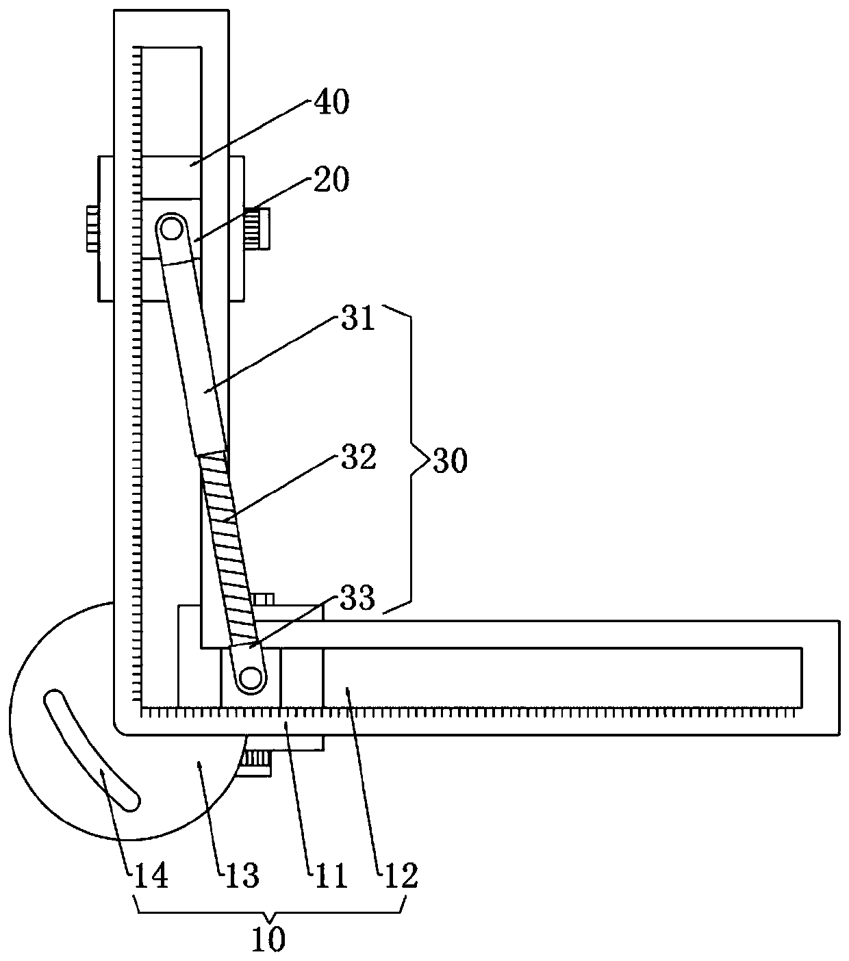
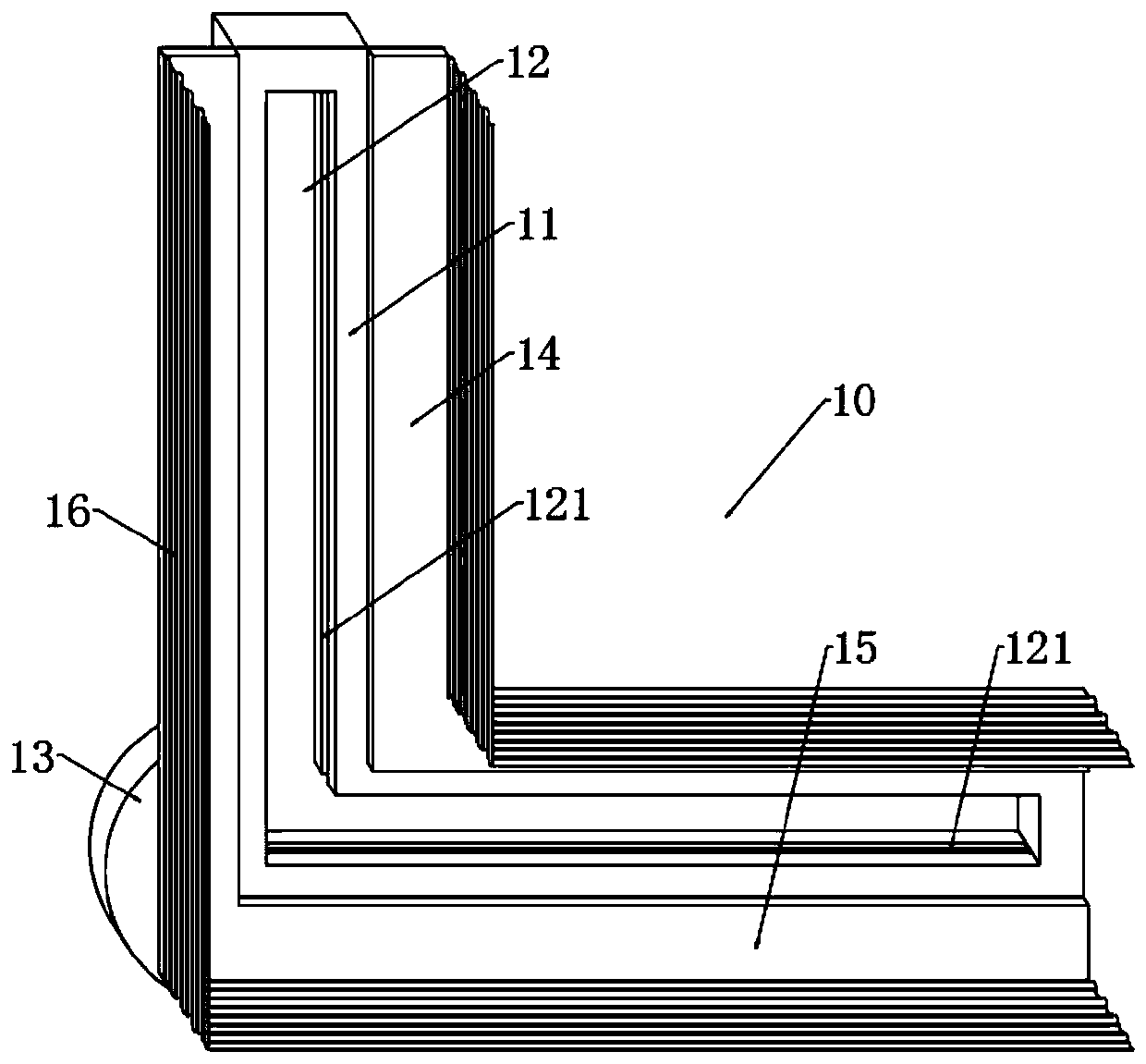
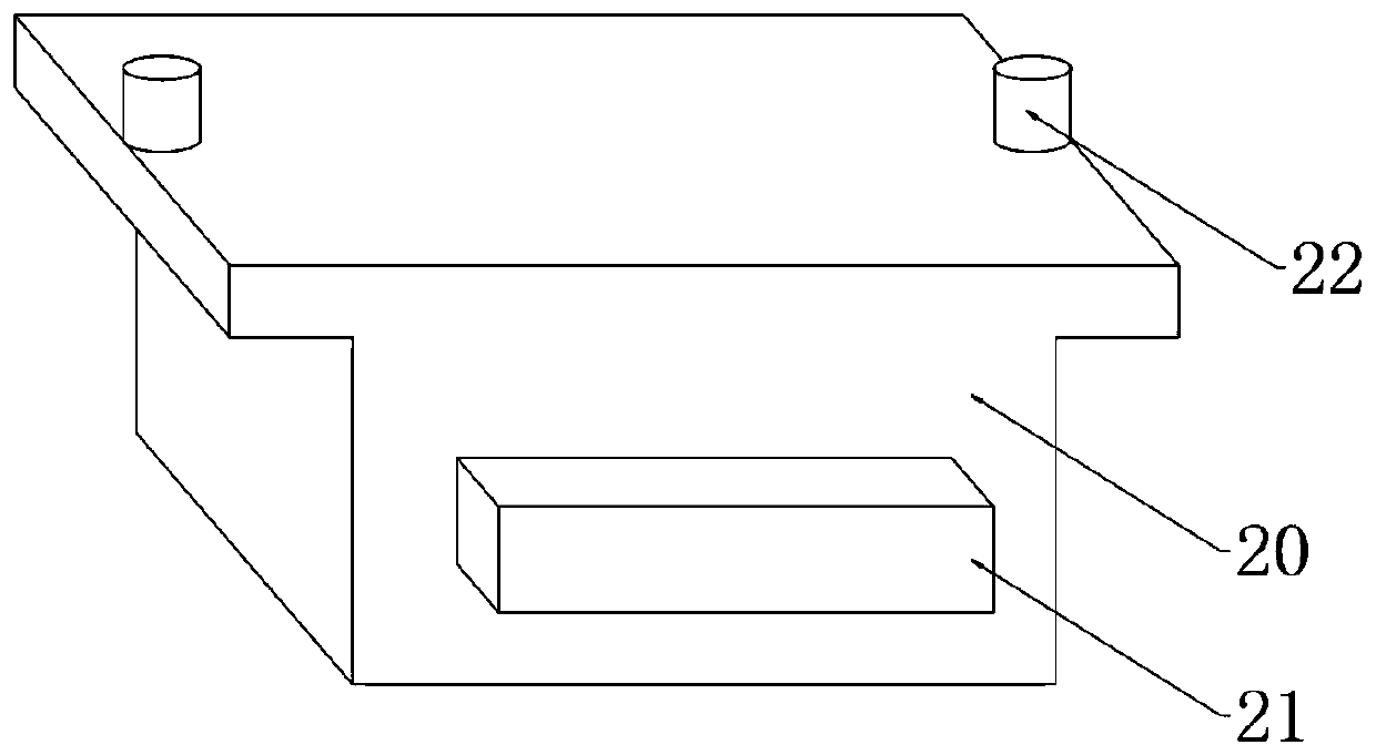
[0031] Such as figure 1 As shown, a construction engineering basement pipeline laying casing groove arrangement excavation device includes an L-shaped guide mechanism 10 and two sets of moving blocks 20 slidably arranged in the L-shaped guide mechanism 10, and the two sets of moving blocks 20 are connected by connecting The rod mechanism 30 is connected, and the connecting rod mechanism 30 comprises a threaded pipe 31 and a threaded rod 32 screwed in the threaded pipe 31. The ends of the threaded pipe 31 and the threaded rod 32 are connected with a connecting plate 33 by bearing rotation, and the connecting plate 33 and The front of the moving block 20 is hingedly connected, and the back of the moving block 20 is provided with a detachable slotting ...


PUM


Abstract

The invention relates to a constructional engineering basement pipeline laying casing pipe groove arrangement digging device, and the device comprises an L type guiding mechanism and two sets of moving blocks arranged in the L type guiding mechanism in sliding form, a link mechanism is arranged between the moving blocks, two ends of the link mechanism are respectively in hinge joint with the moving blocks, and back surfaces of the moving blocks are provided with detachable slotting mechanisms. In the constructional engineering basement pipeline laying casing pipe groove arrangement digging device, the two sets of moving blocks are connected together through the link mechanism, when one set of moving block drives the slotting mechanism to move, the other set of moving block moves with the previous set of moving block under action of the link mechanism, thus, simultaneous slotting of a horizontal groove and a vertical groove is realized, and slotting efficiency is improved. According tothe constructional engineering basement pipeline laying casing pipe groove arrangement digging device, by a guiding function of an L type through hole to the moving blocks, and the grooves formed by the slotting mechanism can be more straighter; and in the constructional engineering basement pipeline laying casing pipe groove arrangement digging device, by rotation of a rotating rod, a cutting disk of corresponding width can be rotated to a position of a transmission shaft, thus, grooves of different width can be formed, and an adjusting process of width of the cutting disk is simplified.

Description

technical field [0001] The invention relates to the technical field of wall grooving, in particular to an excavating device for laying casing grooves for laying pipelines in a construction engineering basement. Background technique [0002] In construction engineering, the basement needs to lay cables or pipes, and it is necessary to dig grooves on the wall for placing casings. According to the actual situation, it is mainly divided into horizontal grooves and vertical grooves. When performing grooves, The slotting is carried out manually by hand-held wall slotting machines. The wall slotting machine can open the wire slots required for construction in one operation, without the need for other tools to operate. [0003] However, there are still the following disadvantages when the wall slotting machine is used for slotting: 1. The slotting machine generates large vibrations during operation, and manual operation is easy to make the slots not completely horizontal or vertical...

Claims


Application Information

Patent Timeline
IPC IPC(8): B28D1/24B28D7/00B28D7/02
CPCB28D1/228B28D1/24B28D7/00B28D7/02
Inventor 吴银国宣守华王爱超贺瑞
Owner ANHUI HUALI CONSTR GRP
Learn More