
Balloon control ring on ring spinning machine

A technology of ring spinning machine and control ring, which is applied in the direction of spinning machine, continuous winding spinning machine, textile and paper making, etc. It can solve the problem that the actuating mechanism cannot be easily integrated into the spinning machine and block the balloon control ring And other issues

Active Publication Date: 2020-08-11
MASCHINENFABRIK RIETER AG
View PDF16 Cites 2 Cited by
  • Summary
  • Abstract
  • Description
  • Claims
  • Application Information

AI Technical Summary

Problems solved by technology

[0006] The disadvantage of this embodiment is that the actuating mechanisms cannot be easily integrated into the spinning machine so that they can be opened or closed simultaneously
Furthermore, it must be possible to block the balloon control ring in different positions and it must be possible for the operator to repair the yarn break in only one position
At the same time, however, the balloon control ring must not obstruct the doffing operation

Method used


Image

  • Balloon control ring on ring spinning machine
  • Balloon control ring on ring spinning machine
  • Balloon control ring on ring spinning machine

Examples


Embodiment Construction

[0032] figure 1 A ring spinning machine 1 according to the invention is schematically shown with a plurality of adjacently positioned spinning stations 2 . The spinning station 2 is arranged in the head 3 along the longitudinal direction X of the ring spinning machine 1 1 and tail 3 2 between. Head 3 of ring spinning machine 1 1 and tail 3 2 Can contain bearings, drives, controls etc. necessary to operate the spinning machine. For example, if figure 1 As further seen on the two spinning stations 2 schematically shown in , each spinning station 2 consists of a roving bobbin 4 located above a drafting system 5 on which a roving 6 is wound. The roving 6 extends from the roving bobbin 4 across a drafting system 5 where the roving is drawn and then guided to a yarn forming element. The endless traveler or ring traveler winds the finished yarn onto the bobbin 7 . Cops 7 are mounted on spindles 8 . figure 1 Also shown are the spindle guide 9 and the ring guide 10 . A balloo...


PUM

PropertyMeasurementUnit
diameteraaaaaaaaaa

Abstract

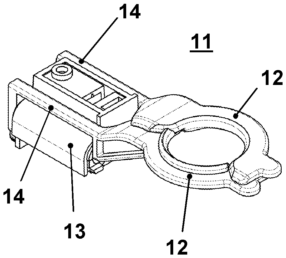
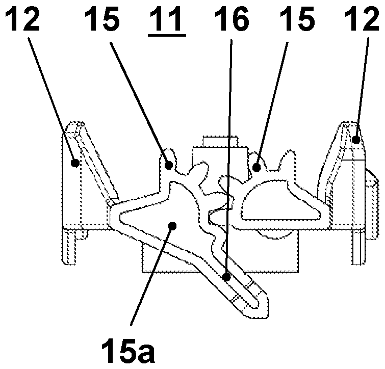
The invention relates to a balloon control ring (11) which is arranged between a thread guide and a ring traveller in a ring spinning machine (1). Advantageously, said balloon control ring consists oftwo half rings (12), wherein the two half rings (12) are pivotably mounted in such a manner that said ring can be opened or folded up. The two half rings (12) may comprise a fork (14), in addition tothe bearing, each of which is guided around the bearing (13), and may comprise engagement means (15) located behind the bearing (13) which engage in each other. The balloon control ring (11) may be opened by a lever (16) or a pinion (18). The invention also relates to a corresponding ring spinning machine (1).

Description

technical field [0001] The invention relates to a balloon control ring for a ring spinning machine according to the independent patent claims. Background technique [0002] Ring spinning machines generally comprise a balloon control ring which is located between the yarn guide and the ring traveler. Without such a balloon control ring, the yarn would assume a strongly bent position and the balloon could become unstable and possibly collapse. To avoid this so-called necking, the balloon is constricted in the middle by a balloon control ring so that two inherently stable smaller balloons are formed. These balloon control rings have various embodiments. A conventional balloon control ring is known, for example, from CH687708 or DE4324587. [0003] DE102005014063 discloses an embodiment in which the balloon control ring is temporarily displaced vertically during yarn thickening in order to prevent expansion of the yarn balloon and thus prevent mass loss or yarn breakage. [...

Claims


Application Information

Patent Timeline
Patent Type & Authority Applications(China)
IPC IPC(8): D01H1/42B65H57/22D01H7/18
CPCD01H1/425D01H7/18
Inventor R.纳格利
Owner MASCHINENFABRIK RIETER AG
Learn More