Switching power supply controller, switching power supply system and switching power supply system power supply method

A switching power supply and controller technology, applied in control/regulation systems, instruments, electrical components, etc., can solve the problems of output voltage DCout load regulation rate and poor dynamic characteristics, and achieve simple topology structure, low system cost, and improved load. Effects of Regulation and Dynamics

Active Publication Date: 2020-08-11
SHANGHAI BRIGHT POWER SEMICONDUCTOR CO LTD
View PDF6 Cites 0 Cited by
  • Summary
  • Abstract
  • Description
  • Claims
  • Application Information

AI Technical Summary

Problems solved by technology

The output voltage DC OUT supplies power to the subsequent load, and in this switching power supply system, when working stably, the operating voltage (that is, the supply voltage) VCC of the control chip U0 is realized by the output voltage DC out through the diode D6 and the VCC sampling capacitor C3 , the VCC sampling capacitor C3 completes the sampling of the output voltage DC out and the power supply to the control chip U0, that is to say, the power supply mode of the control chip U0 is the power supply mode of the output voltage. This power supply mode of the control chip has good standby power consumption. However, since the VCC sampling capacitor C3 is required, and the sampling of the output voltage DC out is not direct sampling, the load regulation and dynamic characteristics of the output voltage DC out are poor.

Method used


Image

  • Switching power supply controller, switching power supply system and switching power supply system power supply method
  • Switching power supply controller, switching power supply system and switching power supply system power supply method
  • Switching power supply controller, switching power supply system and switching power supply system power supply method

Examples


Embodiment Construction

[0042] The technical solutions proposed by the present invention will be described in further detail below in conjunction with the accompanying drawings and specific embodiments. The advantages and features of the present invention will become clearer from the following description. It should be noted that all the drawings are in a very simplified form and use imprecise scales, and are only used to facilitate and clearly assist the purpose of illustrating the embodiments of the present invention. In this article, the meaning of connecting two components includes direct connection or indirect connection through other components.

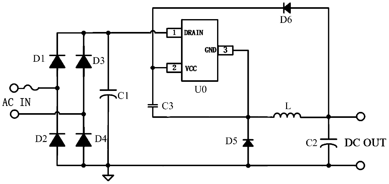
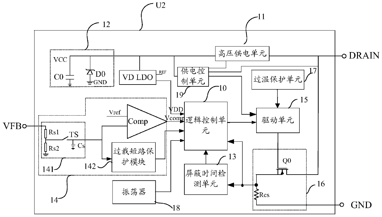
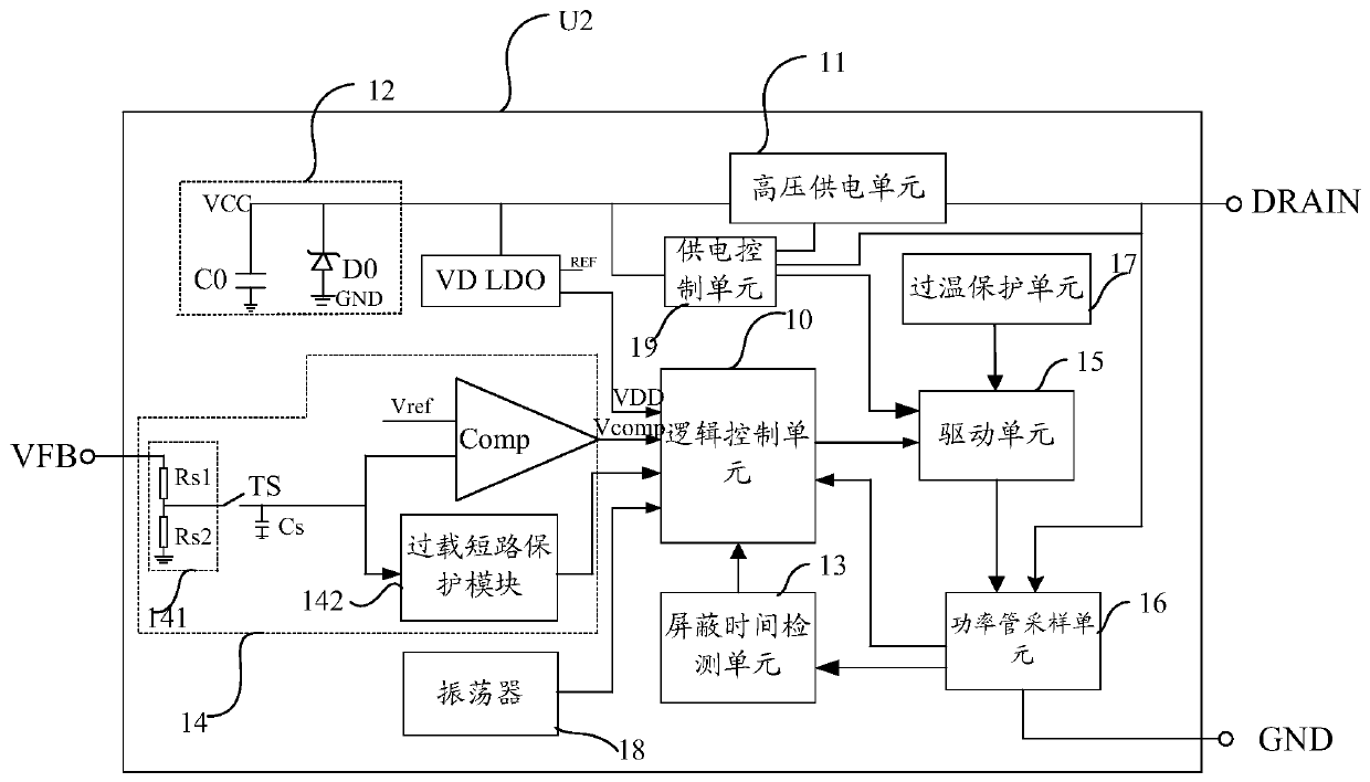
[0043] Please refer to Figure 2 to Figure 4 , an embodiment of the present invention provides a switching power supply controller U2 for controlling the output voltage DC OUT of a switching power supply system. The switching power supply controller U2 includes: a logic control unit 10, a high-voltage power supply unit 11, a built-in energy storage ...


PUM


Abstract

The invention provides a switching power supply controller, a switching power supply system and a switching power supply system power supply method. The switching power supply controller comprises a built-in energy storage unit, a power switching tube sampling unit with a power switching tube, a driving unit and a logic control unit which are positioned in the same packaging body, wherein the driving unit is used for driving the power switching tube to be switched on or switched off under the control of the logic control unit so as to adjust the output voltage of the switching power supply system, and the built-in energy storage unit is used for supplying power to the logic control unit. According to the invention, the hardware consumption of the switching power supply system can be saved,the system power consumption is reduced, and the limitation on the size of the built-in energy storage capacitor is avoided.

Description

technical field [0001] The invention relates to the technical field of switching power supplies, in particular to a switching power supply controller, a switching power supply system and a power supply method for the switching power supply system. Background technique [0002] High-side buck (high-side buck) AC-DC switching power supply systems are widely used in household appliances and electric meters. Standby power consumption, better EMI performance, better usage flexibility, and lower cost. [0003] figure 1 It is a commonly used high side buck AC-DC switching power supply system. The voltage on the AC side of the power grid is rectified by a rectifier bridge composed of diodes D1, D2, D3, and D4, and then output as an output voltage DC OUT after being controlled by the control chip U0, and DC OUT is a fixed value. The output voltage DC OUT supplies power to the subsequent load, and in this switching power supply system, when working stably, the operating voltage (th...

Claims


Application Information

Patent Timeline
Patent Type & Authority Applications(China)
IPC IPC(8): H02M7/217H02M3/156H02M1/08
CPCH02M3/156H02M1/08H02M7/219H02M1/36Y02B70/10
Inventor 江儒龙胡黎强孙顺根郜小茹陈一辉卢鹏飞朱臻张弘
Owner SHANGHAI BRIGHT POWER SEMICONDUCTOR CO LTD
Why Eureka
Try Eureka