
Distributed wireless measurement system and method for transient electromagnetic environment

A technology for electromagnetic environment and wireless measurement, applied in measurement devices, transmission systems, electromagnetic field characteristics, etc., can solve problems such as cables or light being easily broken, not allowed to pass through wiring, and susceptible to interference, etc., to achieve long-term online monitoring, The effect of improving measurement efficiency and measurement accuracy, and expanding the range of use

Active Publication Date: 2020-08-11
STATE GRID CORP OF CHINA +2
View PDF5 Cites 1 Cited by
  • Summary
  • Abstract
  • Description
  • Claims
  • Application Information

AI Technical Summary

Problems solved by technology

Electromagnetic disturbance measurement using cable transmission is susceptible to interference; electromagnetic disturbance measurement using optical fiber is easy to break due to the brittleness of the optical fiber; in addition, because there are many channels in the substation, it is often necessary to walk or pass the car, and the cable or light is easy is broken, and some channels are not allowed to cross the wiring
Therefore, it is not feasible to conduct distributed electromagnetic transient measurements with a large number of cables and optical fiber wiring in the substation

Method used


Image

  • Distributed wireless measurement system and method for transient electromagnetic environment
  • Distributed wireless measurement system and method for transient electromagnetic environment
  • Distributed wireless measurement system and method for transient electromagnetic environment

Examples


specific Embodiment

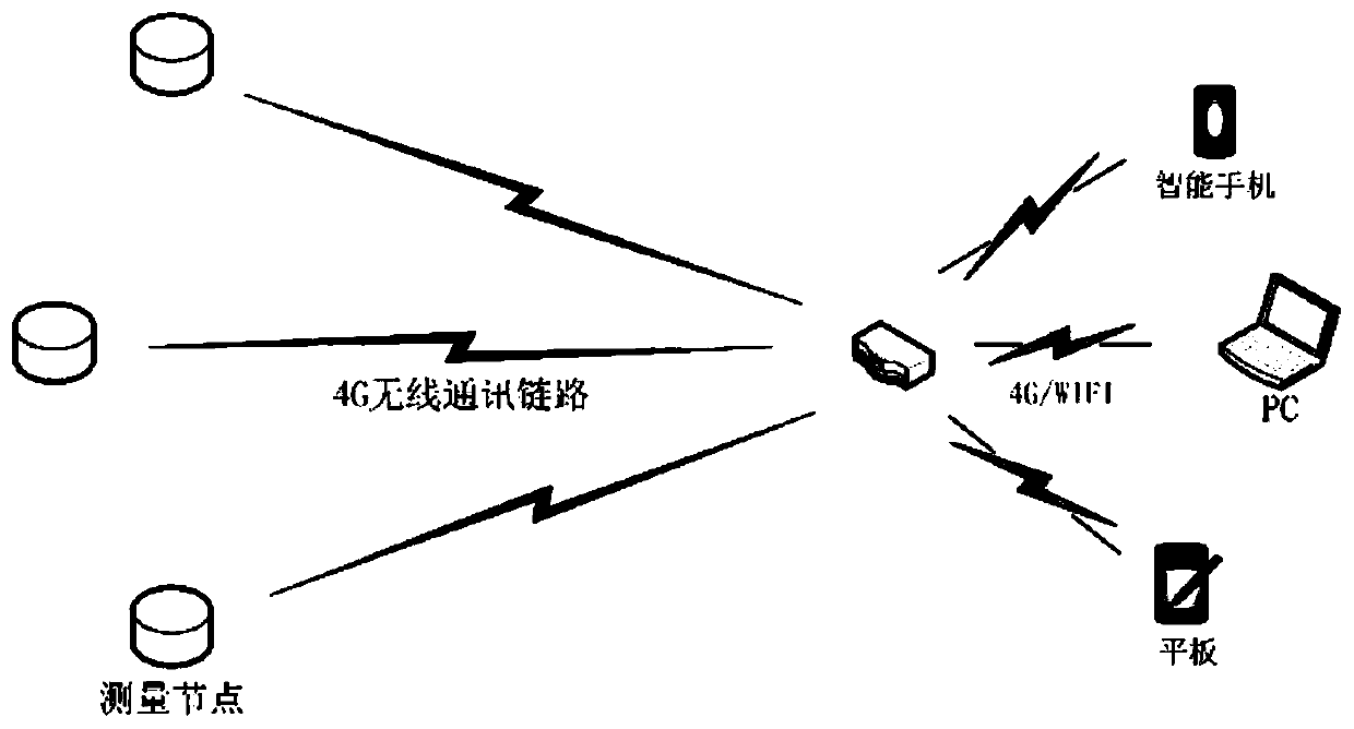
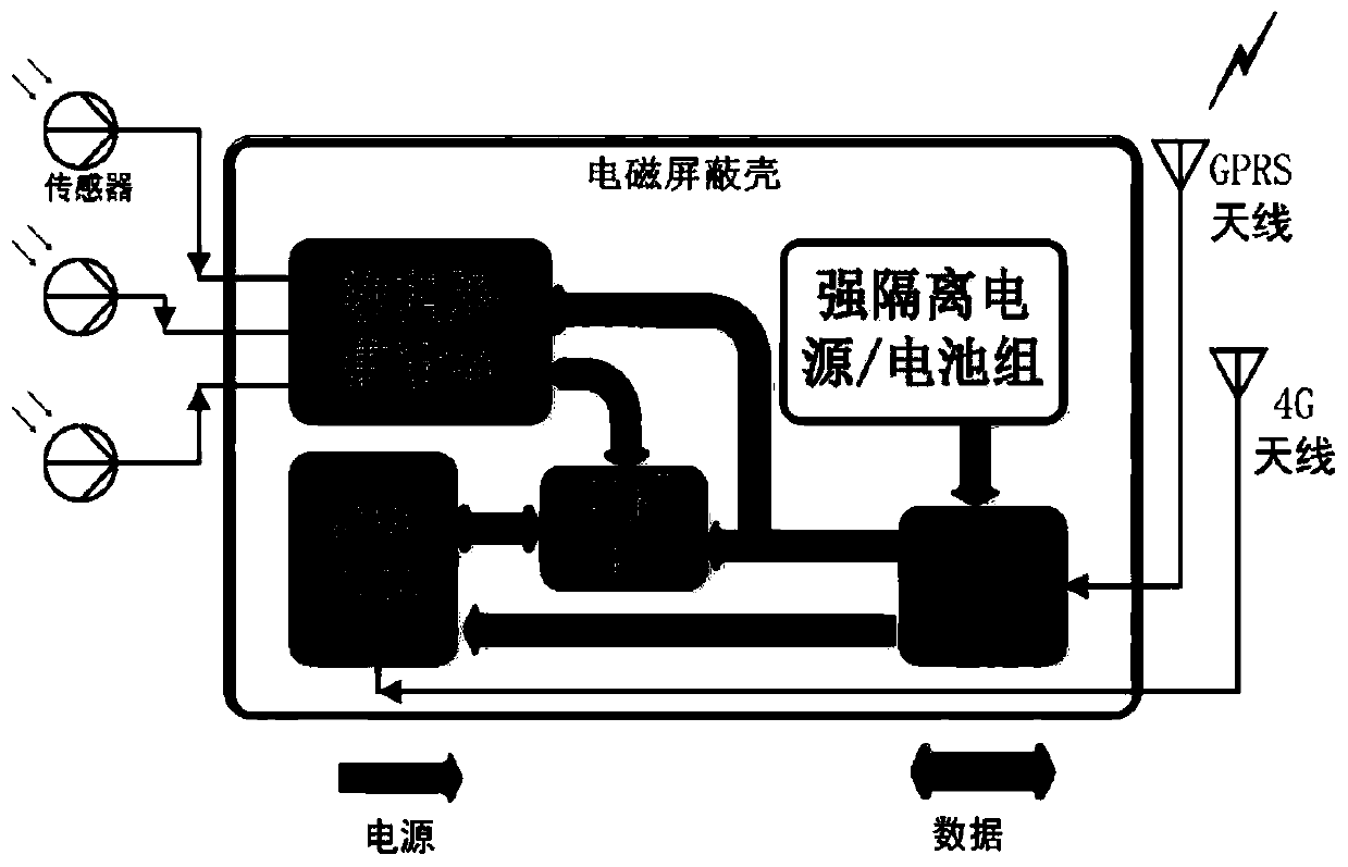
[0082] Please refer to figure 1 , figure 1 It is a schematic diagram of a distributed wireless measurement system for a transient electromagnetic environment. A distributed wireless measurement system for a transient electromagnetic environment in an embodiment of the present invention is composed of multiple front-end measurement nodes, a back-end monitoring and operating device, control software, and a 4G network. The measurement node collects the measurement signal of the sensor and processes and analyzes it. The 4G network transmits images and control signals, and the back-end monitoring and operating equipment displays the desktop image of the controlled industrial computer and human-computer interaction with keys and mice.

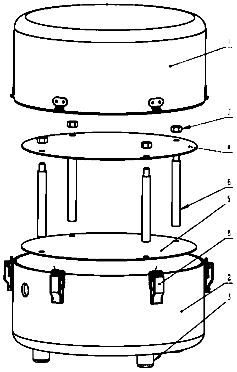
[0083] Please refer to figure 2 , figure 2 It is a schematic diagram of the structure of the shielding shell. The aluminum shielding shell includes an upper barrel body 1, a lower barrel body 2, a foot 3, a pillar 6, an upper mounting plate 4, ...


PUM


Abstract

The invention discloses a distributed wireless measurement system and method for a transient electromagnetic environment. The system comprises a front-end measurement device and rear-end monitoring operation equipment, wherein the front-end measurement device comprises a plurality of measurement nodes; each measurement node comprises an electromagnetic transient sensor, data acquisition equipment,an industrial personal computer, data storage equipment, a router, a power supply module and a shielding shell; the rear-end monitoring operation equipment is used for monitoring and controlling eachmeasurement node, checking the measured electromagnetic transient waveform of each measurement node, carrying out human-computer interaction with the industrial personal computer in each measurementnode, controlling the data acquisition equipment of each measurement node, and drawing a transient electromagnetic distribution diagram in the measurement area according to the corresponding relationbetween the measurement result and the measurement position. Each measurement node and the rear-end monitoring operation equipment are in communication through a 4G or 5G network of a telecom operator, and the plurality of measurement nodes are managed in an account mode. According to the invention, distributed wireless measurement of a transient electromagnetic environment can be realized.

Description

technical field [0001] The invention belongs to the technical field of high-voltage measurement and electromagnetic compatibility, and in particular relates to a distributed wireless measurement system and method for a transient electromagnetic environment. Background technique [0002] There are a large number of switchgears in the substation, such as: isolating switch, circuit breaker, etc.; switching operation is a routine operation of the substation, such as: isolating switch switching no-load transformer, high-voltage unloaded bus, and circuit breaker high-voltage bus and lines, etc. . During the switching operation, especially when the unloaded busbar is used, a strong operating overvoltage and current will be generated on the busbar and the transmission line. At this time, the busbar is equivalent to an antenna, radiating the energy of the transient electromagnetic field to the surrounding space. The measurement equipment (CT, PT and CVT) on the bus or line is direct...

Claims


Application Information

Patent Timeline
IPC IPC(8): G01R29/08G01R19/00H04L29/08H04L12/12
CPCG01R29/0871G01R19/00H04L67/12H04L67/025H04L12/12
Inventor 成林卢江平刘健郭安祥冯南战吴经锋徐伟锋高峰韦邦建石团结刘子瑞王辰曦吴子豪
Owner STATE GRID CORP OF CHINA
Learn More