
Clean room rotating channel capable of isolating air from communication

A technology that blocks air and clean rooms, and is applied in pipeline layout, special buildings, small buildings, etc., and can solve problems such as mutual intrusion

Pending Publication Date: 2020-08-11
龚琳涵
View PDF0 Cites 0 Cited by
  • Summary
  • Abstract
  • Description
  • Claims
  • Application Information

AI Technical Summary

Problems solved by technology

[0004] However, when the staff enters and exits, the door of the clean room is inevitably opened and closed as a passage to enter and exit the clean room. The original stable state of the adjacent clean room environment is disturbed, and the air in the isolated clean room passes through. The opening of the door directly colludes, and there is a phenomenon of mutual intrusion: on the one hand, the air in the clean room with a relatively large absolute pressure difference invades a large number of clean rooms with a relatively small absolute pressure difference through the opened clean room door; , the air in the clean room with a relatively small absolute pressure difference, at the moment of opening the door, due to the uncertainty of the air flow direction, more or less intrudes into the clean room with a relatively large absolute pressure difference with the reverse airflow or attached to the body of the staff

Method used


Image

  • Clean room rotating channel capable of isolating air from communication
  • Clean room rotating channel capable of isolating air from communication
  • Clean room rotating channel capable of isolating air from communication

Examples


Embodiment

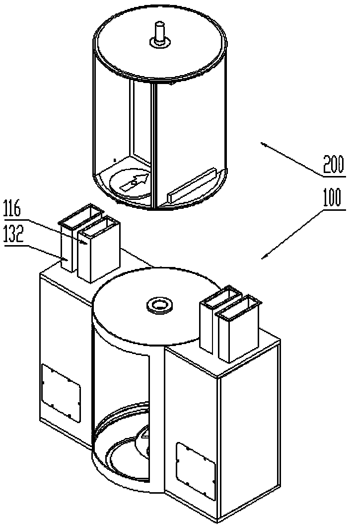
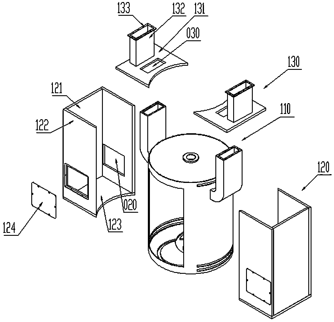
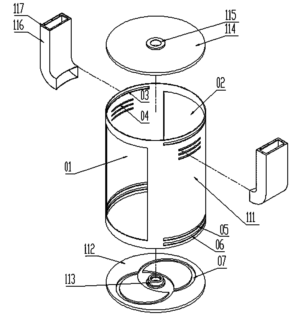
[0056] A clean room rotating tunnel with barrier air collusion, including PLC control cabinet, see figure 1 , including a cylindrical base body 100 and a manned rotary unit 200; see figure 2 , Figure 8 and Figure 9 , the cylindrical base body 100 includes a cylindrical body unit 110 and a negative pressure chamber 3 sealed on both sides of the cylindrical body unit 110, and a suction pipe 132 is arranged on the top of the negative pressure chamber 3; see image 3 The cylinder unit 110 includes a cylinder body 111 and an air inlet pipe 116, and the air inlet pipe 116 is integrally sealed and fixed on the upper part of the cylinder wall on the left and right sides of the periphery of the cylinder body 111; The passage opening includes the front passage opening 01 and the rear passage opening 02. Taking the axial section of the cylinder 111 facing the passage opening as the reference projection plane, the projection of the front passage opening 01 on the reference projection...


PUM


Abstract

The invention discloses a clean room rotating channel capable of isolating air from communication. The clean room rotating channel comprises a PLC control cabinet, a cylinder machine seat body and a manned rotating unit, wherein the cylinder machine seat body comprises a cylinder body unit and a negative pressure cavity, an air suction pipe is arranged at the top of the negative pressure cavity, the cylinder body unit comprises a cylinder body and an air inlet pipe, the air inlet pipe is integrally sealed and fixedly connected to the upper portions of the left and right cylinder walls of the periphery of the cylinder body, channel openings are formed in the front and rear cylinder walls of the cylinder body, the air inlet pipe communicates with an inner cavity of the cylinder body throughan air inlet air port, the negative pressure cavity communicates with the inner cavity of the cylinder body through an upper air suction port, an air return air port and a lower air suction port, a top rotating middle shaft and a bottom rotating middle shaft are arranged at the top and the bottom of the manned rotating unit respectively, the manned rotating unit is in shaft connection with the inner cavity of the cylinder body unit through the top rotating middle shaft and the bottom rotating middle shaft; and a driving motor is in circuit connection with the PLC control cabinet. The clean room rotating channel has the advantages that air can be isolated from communication, the channel function can be achieved, and the air communication also can be prevented.

Description

technical field [0001] The invention relates to the technical field of clean room passage equipment, in particular to a rotating channel used inside a clean room, in particular to a clean room rotating channel that blocks air from colluding. Background technique [0002] In the pharmaceutical, medical, electronic and other industries, clean rooms are widely used. Although the purpose of clean rooms varies widely, they are common in how to prevent cross-contamination. The mutual intrusion of clean indoor and outdoor air is the cause of cross-contamination. one of the reasons. [0003] Generally, the absolute pressure difference of a clean room with a relatively high cleanliness level is relatively large for a clean room with a relatively low cleanliness level; Poor, air flow direction, cleanliness, etc. are all in an ideal balance state, which is also the most stable state of the clean room environment. [0004] However, when the staff enters and exits, the door of the clea...

Claims


Application Information

Patent Timeline
IPC IPC(8): E04H1/12F24F13/02
CPCE04H1/1277F24F13/02
Inventor 龚琳涵王蓉
Owner 龚琳涵
Learn More