Metal heat treatment furnace capable of achieving continuous feeding conveniently

A metal heat treatment and heat treatment furnace technology, applied in heat treatment furnaces, heat treatment equipment, furnaces, etc., can solve problems such as laborious operation of workers, safety hazards at high temperature of the furnace door, and impact on metal heat treatment work efficiency, so as to avoid losses and improve safety , high work efficiency

Active Publication Date: 2020-08-11
山东恒玖热处理科技有限公司
View PDF8 Cites 4 Cited by
  • Summary
  • Abstract
  • Description
  • Claims
  • Application Information

AI Technical Summary

Problems solved by technology

[0003] The metal heat treatment furnaces designed for the metal heat treatment process in the prior art are usually in the form of a single channel, so that when the metal parts are heat treated, the feeding and discharging are realized from one furnace door, thus As a result, the loading of the metal heat treatment furnace cannot be continuously loaded, which affects the work efficiency of the production line for heat treatment of metals, and the traditional heat treatment furnace workers are too close to the furnace door during loading and unloading, which is not only due to The high temperature near the furnace door makes it difficult for workers to operate, and there are certain safety hazards at the high temperature of the furnace door

Method used


Image

  • Metal heat treatment furnace capable of achieving continuous feeding conveniently
  • Metal heat treatment furnace capable of achieving continuous feeding conveniently
  • Metal heat treatment furnace capable of achieving continuous feeding conveniently

Examples


Embodiment Construction

[0028] The technical solutions in the embodiments of the present invention will be clearly and completely described below in conjunction with the accompanying drawings in the embodiments of the present invention. Obviously, the described embodiments are only some of the embodiments of the present invention, not all of them. Based on the embodiments of the present invention, all other embodiments obtained by persons of ordinary skill in the art without creative work all belong to the protection scope of the present invention.

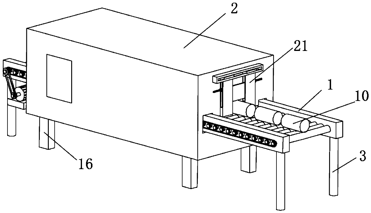
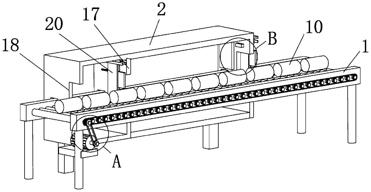
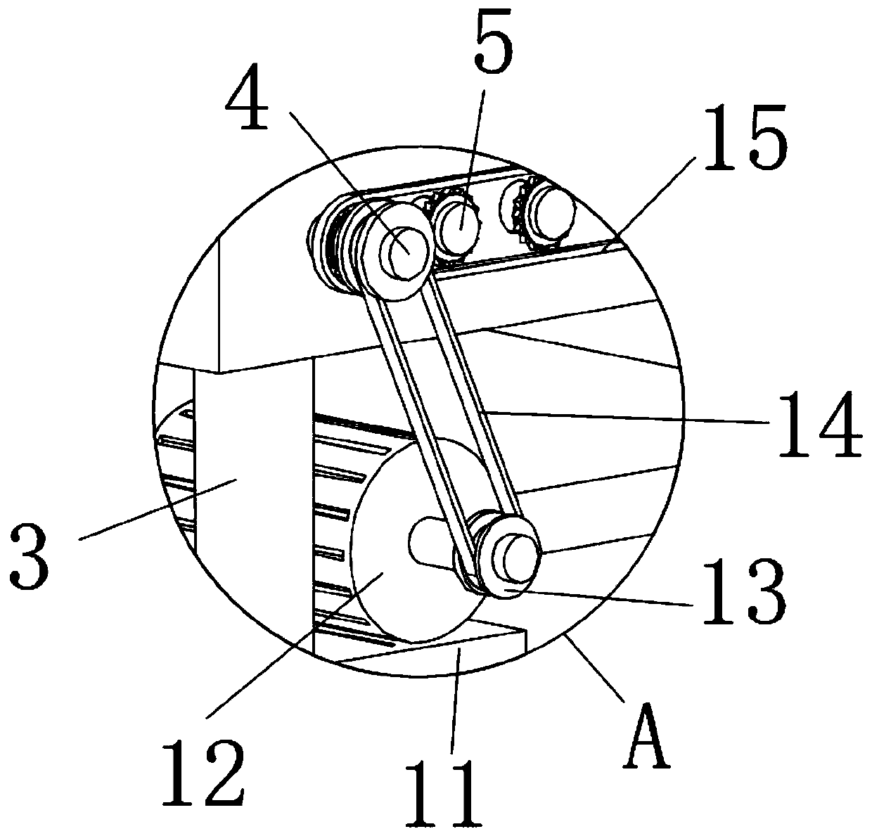
[0029] see Figure 1-9 , the present invention provides a technical solution: a metal heat treatment furnace convenient for continuous feeding, including a conveying mechanism 1 and a heat treating furnace 2, the conveying mechanism 1 is composed of two symmetrically arranged mounting plates and a The main roller shaft 4 and the driven roller shaft 5 are composed of a plurality of driven roller shafts 5 evenly arranged on the rear side of the main roller...


PUM


Abstract

The invention discloses a metal heat treatment furnace capable of achieving continuous feeding conveniently. The metal heat treatment furnace comprises a conveying mechanism and a heat treatment furnace body, and is characterized in that the conveying mechanism is composed of two symmetrically-arranged mounting plates, a driving roller shaft and driven roller shafts, wherein the driving roller shaft and the driven roller shafts are arranged between the two mounting plates; the multiple driven roller shafts are evenly arranged on the rear side of the driving roller shaft; first-stage supportinglegs are fixedly welded to the two ends of the lower surface of each mounting plate, and rotating holes are evenly formed in the sides of plate bodies of the mounting plates; ball bearings are arranged at the two ends of a shaft body of each of the driving roller shaft and the driven roller shafts, and roller shaft structures are rotationally mounted in the rotating holes in the mounting plates of the conveying mechanism through the ball bearings; chain wheels are mounted on rod bodies of the driving roller shaft and the driven roller shaft, the length of the driving roller shaft is larger than that of the driven roller shafts, and a second-stage belt wheel is arranged at the tail end of the driving roller shaft; and the conveying mechanism is arranged in a cavity of the heat treatment furnace body, and therefore materials are continuously fed into the heat treatment furnace body, and compared with feeding and discharging of a traditional single furnace door, the work efficiency of the metal heat treatment furnace is higher.

Description

technical field [0001] The invention relates to the related technical field of metal heat treatment, in particular to a metal heat treatment furnace convenient for continuous feeding. Background technique [0002] Metal heat treatment is to put the metal material in a certain medium to heat, keep warm, and cool down. By heating, the metal material reaches the phase transition temperature and changes its internal metallographic structure, so as to improve the performance of the metal material to meet the needs of the use occasion. . In the heat treatment process of metals, metal heat treatment furnaces are necessary tooling. [0003] The metal heat treatment furnaces designed for the metal heat treatment process in the prior art are usually in the form of a single channel, so that when the metal parts are heat treated, the feeding and discharging are realized from one furnace door, thus As a result, the loading of the metal heat treatment furnace cannot be continuously load...

Claims


Application Information

Patent Timeline
Patent Type & Authority Applications(China)
IPC IPC(8): C21D9/00
CPCC21D9/0018
Inventor 郎露枫
Owner 山东恒玖热处理科技有限公司
Why Eureka
Try Eureka