
High-voltage charge-discharge and leakage circuit integrated topological structure and device for vehicle

A vehicle-used, gating circuit technology, applied in the direction of electrical devices, circuit devices, emergency protection circuit devices for limiting overcurrent/overvoltage, etc., can solve the problem of reducing system reliability, increasing overall cost, and numerous components problem, to achieve the effect of improving system reliability, increasing design margin, and reducing the number of components

Inactive Publication Date: 2020-08-11
泰安航天特种车有限公司
View PDF0 Cites 0 Cited by
  • Summary
  • Abstract
  • Description
  • Claims
  • Application Information

AI Technical Summary

Problems solved by technology

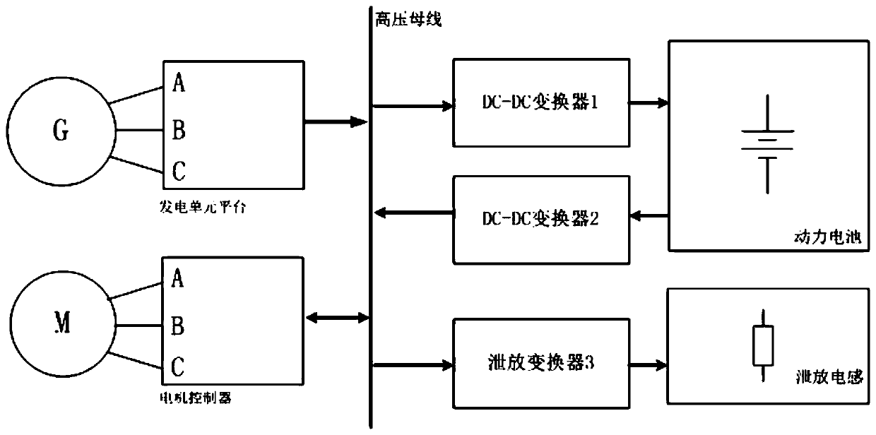
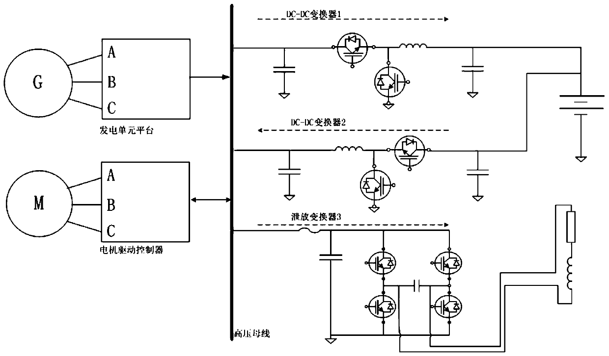
When the bus voltage is too high and the power battery is saturated, the energy of the high-voltage bus is resonantly discharged through the discharge converter 3 (H4 bridge IGBT module), which has many components and complex circuits. Sex, too many power components occupy more space, reduce system reliability and increase overall cost

Method used


Image

  • High-voltage charge-discharge and leakage circuit integrated topological structure and device for vehicle
  • High-voltage charge-discharge and leakage circuit integrated topological structure and device for vehicle
  • High-voltage charge-discharge and leakage circuit integrated topological structure and device for vehicle

Examples


Embodiment 1

[0057] As mentioned in the background art, due to the special application of military hybrid special vehicles, too many power components occupy more space, reduce system reliability and increase overall cost.

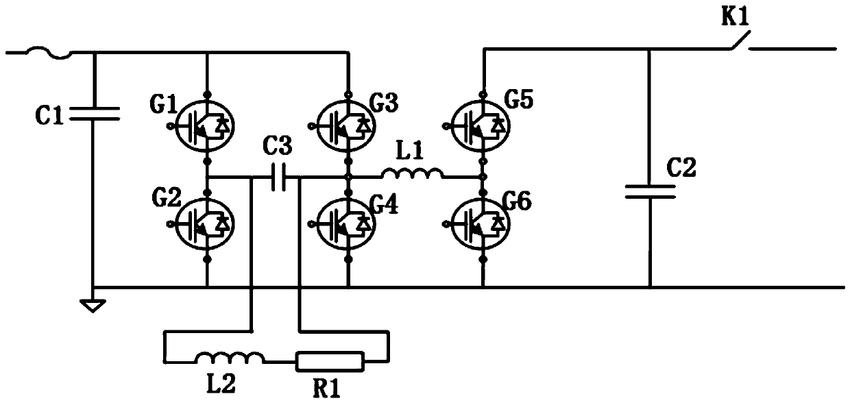
[0058] Therefore, Embodiment 1 of the present disclosure provides a gating circuit, such as image 3 As shown, the gating circuit includes six switch tubes G1-G6, a first capacitor C1, a second capacitor C2, a third capacitor C3, a first inductor L1, a second inductor L2 and a first resistor R1;

[0059] The collectors of the first switching tube G1 and the third switching tube G3 are both connected to the bus bar, the first switching tube is connected in series with the second switching tube, the third switching tube is connected in series with the fourth switching tube, and the fifth switching tube G5 The collector of the power battery is connected to the positive terminal of the power battery, the fifth switching tube has a sixth switching tube G6 connected in series...

Embodiment 2

[0065] Embodiment 2 of the present disclosure provides an integrated topological structure of a high-voltage charging and discharging circuit for a vehicle, such as Figure 4 As shown, it includes a bus bar, a power battery and the gating circuit described in Embodiment 1, and the gating circuit is connected in series between the bus bar and the power battery;

[0066] By controlling the time-sharing gating and closing of the six switching tubes, the forward and reverse BUCK type DC-DC step-down energy conversion between the busbar and the power battery and the energy discharge when the busbar voltage is too high are realized.

Embodiment 3

[0068] Embodiment 3 of the present disclosure provides a vehicle busbar feeding method, which is used to charge the battery through the busbar voltage through the integrated converter, such as Figure 5 As shown, the topology described in Embodiment 2 is used.

[0069] The high-voltage bus energy passes through the G3 insulated gate bipolar triode, the body diode of the inductor L1 and G5 to realize the BUCK chopper converter, and charges the battery after being filtered by the capacitor C2 (shown by the solid arrow in the figure), and disconnects the G3 tube During this period, the G4 body diode freewheels (shown by the dotted arrow on the way).

[0070] Generally speaking, the high-voltage bus is the input terminal, and devices such as G3, G4, G5, L1, C1, and C2 form a BUCK-type chopper power supply from left to right to charge the battery.


PUM


Abstract

The invention provides a high-voltage charge-discharge and leakage circuit integrated topological structure and device for a vehicle and belongs to the technical field of military hybrid special vehicles. The structure comprises six switching tubes, a first capacitor, a second capacitor, a third capacitor, a first inductor, a second inductor and a first resistor; the six switching tubes form an H6-like inverter bridge structure; the third capacitor is connected between the emitter of the first switching tube and the emitter of the third switching tube; the first inductor is connected between the emitter of the third switching tube and the emitter of the fifth switching tube; the third capacitor is connected with at least one first resistor and at least one second inductor in parallel. Three power supply management functions are integrated, and therefore, the size is reduced, the weight is reduced, the space is saved, the complexity of system installation, the complexity of wiring harness connection and the complexity of control logic are reduced, and system reliability is improved.

Description

technical field [0001] The present disclosure relates to the technical field of military hybrid special vehicles, in particular to an integrated topological structure and device of a high-voltage charging, discharging and discharging circuit for a vehicle. Background technique [0002] The statements in this section merely provide background information related to the present disclosure and may not necessarily constitute prior art. [0003] With the development of the global electric vehicle industry and the accumulation of applications, the technologies of pure electric vehicles, extended range and hybrid vehicles are becoming more and more mature. From this, it is derived to the military field, and the electrification transformation of military vehicles, operating vehicles, transport vehicles and other vehicles is carried out, whether it is information transformation, intelligent upgrade or vehicle power performance, high reliability, easy maintenance, strong concealment, ...

Claims


Application Information

Patent Timeline
IPC IPC(8): B60L3/00B60L58/10H02H9/04
CPCB60L3/0023B60L58/10H02H9/04Y02T10/70
Inventor 王成桥朱学斌张志坚万存才陈振华李强曹彦博王广羽刘庆封帆
Owner 泰安航天特种车有限公司
Learn More