Oscillation module and chip electrifying method

A technology of oscillation module and electrical method, which is applied in the direction of electrical components, electric pulse generation, pulse generation, etc., can solve the problems of slow power-on process, poor clock signal duty ratio accuracy, low power supply voltage, etc., and achieve power-on power consumption Effective, power-on power consumption control, avoiding the effect of reset failure

Pending Publication Date: 2020-08-07
SHANGHAI HUAHONG GRACE SEMICON MFG CORP
View PDF3 Cites 0 Cited by
  • Summary
  • Abstract
  • Description
  • Claims
  • Application Information

AI Technical Summary

Problems solved by technology

[0003] However, when the power-on reset circuit releases the POR signal, there will be a problem that the voltage reached by the power supply is lower than the voltage that can ensure the normal operation of the integrated circuit system
Taking the slow power-on process of an integrated circuit system whose normal working voltage is a high-voltage threshold (1.65V to 5.5V) as an example, when the power-on reset circuit releases the POR signal, the minimum voltage reached by the power supply voltage is about 1V, which will affect the integrated circuit. The normal reset of the circuit system adversely affects the
[0004] Related technologies usually use a ring oscillator to wait for the power supply voltage to reach the normal operating voltage, but the duty cycle accuracy of the clock signal generated by the ring oscillator is poor, and its power consumption varies greatly with the power supply voltage

Method used


Image

  • Oscillation module and chip electrifying method
  • Oscillation module and chip electrifying method
  • Oscillation module and chip electrifying method

Examples


Embodiment Construction

[0029] The technical solutions in this application will be clearly and completely described below in conjunction with the accompanying drawings. Apparently, the described embodiments are part of the embodiments of this application, not all of them. Based on the embodiments in this application, all other embodiments obtained by persons of ordinary skill in the art without making creative efforts belong to the scope of protection of this application.

[0030] In the description of this application, it should be noted that the terms "center", "upper", "lower", "left", "right", "vertical", "horizontal", "inner", "outer" etc. The indicated orientation or positional relationship is based on the orientation or positional relationship shown in the drawings, and is only for the convenience of describing the present application and simplifying the description, rather than indicating or implying that the referred device or element must have a specific orientation, use a specific orientati...


PUM


Abstract

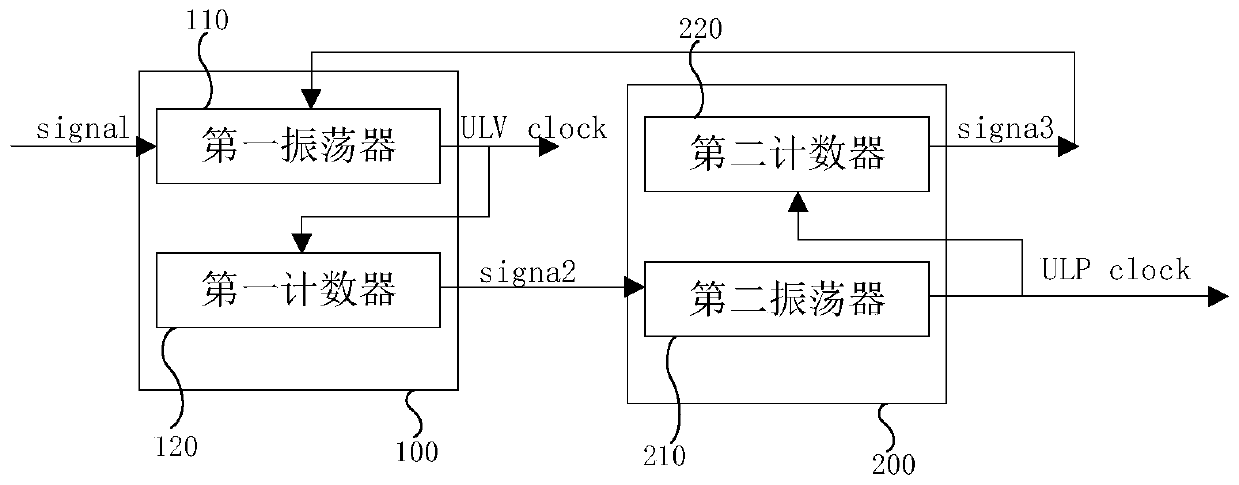
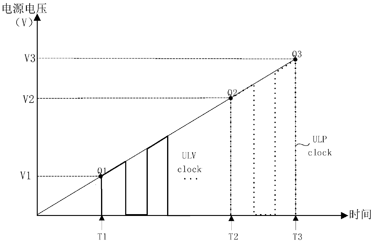
The invention relates to the technical field of semiconductor integrated circuits, in particular to an oscillation module and a chip electrifying method. The oscillation module comprises a first oscillation unit and a second oscillation unit which are cascaded, wherein the first oscillation unit is used for outputting a first clock signal when receiving a first trigger signal and generating a second trigger signal when the number of pulses of the first clock signal reaches a first threshold value; and the second oscillation unit is used for outputting a second clock signal to an integrated circuit system when receiving the second trigger signal and generating a third trigger signal when the number of pulses of the second clock signal reaches a second threshold value, and the third triggersignal is used for controlling the first oscillation unit to stop outputting the first clock signal. According to the oscillation module provided by the invention, the reset failure of the integratedcircuit can be avoided while low-voltage starting is realized, so that the electrifying power consumption of the integrated circuit system is effectively controlled.

Description

technical field [0001] The present application relates to the technical field of semiconductor integrated circuits, in particular to an oscillation module and a chip power-on method. Background technique [0002] In the field of semiconductor integrated circuit technology, the power-on process of the system is a process of slowly climbing the power supply voltage. During this process, the integrated circuit system remains static until the power supply voltage reaches a predetermined voltage, and the power-on reset (POR: Power OnReset) circuit will release The POR signal initializes the integrated circuit system, and after the initialization is completed, the integrated circuit starts to work normally. [0003] However, when the power-on reset circuit releases the POR signal, there will be a problem that the voltage reached by the power supply is lower than the voltage that can ensure the normal operation of the integrated circuit system. Taking the slow power-on process of ...

Claims


Application Information

Patent Timeline
Patent Type & Authority Applications(China)
IPC IPC(8): H03K3/012
CPCH03K3/012Y02D10/00
Inventor 袁志勇
Owner SHANGHAI HUAHONG GRACE SEMICON MFG CORP
Why Eureka
Try Eureka