Convenient photovoltaic module mounting bracket and processing and mounting method

A technology of photovoltaic modules and mounting brackets, which is applied to the support structure of photovoltaic modules, photovoltaic power generation, photovoltaic modules, etc., and can solve the problems of low power generation efficiency of photovoltaic modules on the back side, many installation procedures of photovoltaic support systems, troublesome disassembly of photovoltaic modules, etc. , to achieve the effect of reducing the complex installation process, reducing the load-bearing requirements, and easy installation

Active Publication Date: 2020-08-07
SUQIAN COLLEGE
View PDF8 Cites 0 Cited by
  • Summary
  • Abstract
  • Description
  • Claims
  • Application Information

AI Technical Summary

Problems solved by technology

[0006]Due to the many and complicated installation procedures of the photovoltaic support system, the above-mentioned installation method takes a lot of time to lock the bolts, nuts and screws. Each group of photovoltaic modules has at least Four fixed points, side-by-side photovoltaic modules need to be fixed by screws and pressure blocks, which has the disadvantages of time-consuming, labor-intensive materials, long installation period, and high safety risks; industrial and commercial roofs often encounter color steel tiles, and general color steel tiles It needs to be replaced in about 10 years, so dismantling the photovoltaic modules is even more troublesome, and when there are many procedures, it is very dangerous to work on the corroded color steel tile roof
Especially when the top of the roof ridge runs east-west, the power generation efficiency of the photovoltaic modules on the back side of the sun is low if the conventional tile installation bracket is used

Method used


Image

  • Convenient photovoltaic module mounting bracket and processing and mounting method
  • Convenient photovoltaic module mounting bracket and processing and mounting method
  • Convenient photovoltaic module mounting bracket and processing and mounting method

Examples


Embodiment

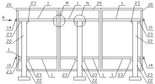
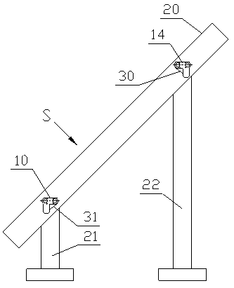
[0065] like figure 1 , 2 As shown, the two groups of profile bodies 1 pass through the first mounting groove 30 and the second mounting groove 31 on the frame 20 of the photovoltaic module, and then are fixedly connected to the first column 21 and the second column 22 through the screw assembly 24 and the connecting plate 23 respectively; The first installation groove 30 and the second installation groove 31 are preferably symmetrical structures, which can realize self-locking after the installation of two groups of profile main bodies 1; 1. The frame wall of the second installation groove 31 is matched and fastened.

[0066] like image 3 As shown, the end surface of the profile main body 1 has a first through hole 2, an end cover screw hole 3, a screw groove 4, a main rib 5, a second through hole 6, and a card groove 7. The first through hole 2 and the second through hole 6 are symmetrical The structure can reduce the weight of the whole body and at the same time can inst...


PUM


Abstract

The invention discloses a convenient photovoltaic module mounting bracket which mainly comprises a sectional material body, a photovoltaic module frame, a first stand column and a second stand column.The sectional material body is connected with the photovoltaic module frame, and is further connected with the first stand column and the second stand column, and the two groups of sectional materialbody penetrate through a first mounting groove and a second mounting groove formed in the photovoltaic module frame and then are fixedly connected with the first stand column and the second stand column through connecting plates and screw assemblies respectively; and the two ends of the sectional material body are tightly connected with the photovoltaic assembly frame through a first end cover and a second end cover. According to the invention, a bracket track, a cross beam and other profiles of the photovoltaic module are combined into a whole and are effectively embedded into the mounting grooves of the photovoltaic module frame, a group of multiple photovoltaic modules can be combined, connected and fixed, the use amount of the cross beam, the bracket, pressing blocks, a screw assemblyand auxiliary materials is greatly reduced, and the investment cost of a power station is reduced.

Description

technical field [0001] The invention relates to the technical field of photovoltaic power generation, in particular to a convenient mounting bracket for photovoltaic modules. Background technique [0002] The solar photovoltaic support is a special support designed for placing, installing and fixing solar panels in the solar photovoltaic power generation system. Common materials are aluminum alloy, carbon steel and stainless steel. [0003] The solar support system related products are made of carbon steel and stainless steel. The surface of the carbon steel is hot-dip galvanized, and it will not rust after 30 years of outdoor use. The solar photovoltaic support system is characterized by no welding, no drilling, 100% adjustable, and 100% reusable. [0004] In order to maximize the power output of the entire photovoltaic power generation system, combined with the geography, climate and solar resource conditions of the construction site, the support structure that fixes the...

Claims


Application Information

Patent Timeline
Patent Type & Authority Applications(China)
IPC IPC(8): H02S20/00H02S20/23H02S30/10
CPCH02S20/00H02S20/23H02S30/10Y02E10/50Y02B10/10
Inventor 施允洋唐友亮刘方方房开拓虞洋
Owner SUQIAN COLLEGE
Why Eureka
Try Eureka