Accelerated power generation system and accelerated power generation control method thereof

A technology for power generation systems and generators, applied in the direction of controlling mechanical energy, connecting with control/drive circuits, electrical components, etc., can solve the problems of damage to the service life of power units, slow start, excessive torque, etc., to achieve light load, improve Service life, impact reduction effect

Inactive Publication Date: 2020-08-07
黄明实
View PDF6 Cites 5 Cited by
  • Summary
  • Abstract
  • Description
  • Claims
  • Application Information

AI Technical Summary

Problems solved by technology

A general generator set is composed of a power unit (mostly a three-phase motor, diesel engine or gasoline engine), a generator set and a power distribution control device. After success, the power unit will start the generator set to work stably and continuously, so as to continuously supply electric energy to the outside; since the power unit and the generator set are started at the same time, the generator set is slow to start due to its own mass inertia, and the generator set starts and The torque will be too large during the speed-up process. For this reason, the power configuration of the power unit that is required to start is relatively high, and it is often difficult to start or even unable to start. After starting, the speed-up process is relatively slow, and the power unit performs a When speed is increased, it is limited by the driving force. Even if a larger force is added, the effect of speed increase will not be achieved, and even the power unit will be seriously damaged. The impact of the power unit will seriously damage the service life

Method used


Image

  • Accelerated power generation system and accelerated power generation control method thereof
  • Accelerated power generation system and accelerated power generation control method thereof

Examples


Embodiment Construction

[0022] In order to make the object, technical solution and advantages of the invention clearer, the invention will be further described in detail below with reference to the drawings and preferred embodiments. However, it should be noted that many of the details listed in the specification are merely for the reader to have a thorough understanding of one or more aspects of the invention, and these aspects of the invention can be practiced without these specific details.

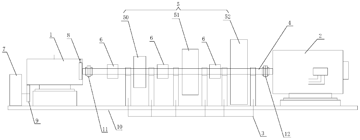
[0023] like figure 1 As shown, an accelerated power generation system according to the invention includes a support base 10 and a power motor 1 installed on the support base 1, a generator 2 and a bearing seat 3, and the output shaft of the power motor 1 and the generator 2 There are several transmission shafts 4 arranged coaxially between the input shafts, and each transmission shaft 4 is installed on the support base 1 through several bearing seats 3, and the output shaft of the power motor 1 passes through...


PUM


Abstract

The invention discloses an accelerated power generation system and an accelerated power generation control method thereof. The system comprises a supporting base and a power motor, a generator and a bearing seat which are installed on the supporting base. A plurality of sections of transmission shafts which are coaxially arranged are arranged between an output shaft of the power motor and an inputshaft of the generator; each section of transmission shaft is mounted on the supporting base through a plurality of bearing bases; the power motor is in transmission connection with a head end of thetransmission shaft through a first coupler; the generator is in transmission connection with the transmission shaft through a second coupler, multiple stages of flywheels with the diameters graduallyincreased are sequentially installed on the transmission shaft between the power motor and the generator, and a clutch is arranged on the transmission shaft on one side of an input rotor of each stage of flywheel. The rotating speed of the power motor can be rapidly increased, the power motor can be rapidly started under the light load condition, the speed increasing effect is effectively improved, the impact borne by the power motor is reduced, and the service life of the power motor is prolonged.

Description

technical field [0001] The invention belongs to the technical field of generators, and in particular relates to an accelerated power generation system and an accelerated power generation control method thereof. Background technique [0002] The power generator is generally a system composed of a starter motor, a generator and other auxiliary parts, generally called a generator set. A general generator set is composed of a power unit (mostly a three-phase motor, diesel engine or gasoline engine), a generator set and a power distribution control device. After success, the power unit will start the generator set to work stably and continuously, so as to continuously supply electric energy to the outside; since the power unit and the generator set are started at the same time, the generator set is slow to start due to its own mass inertia, and the generator set starts and The torque will be too large during the speed-up process. For this reason, the power configuration of the p...

Claims


Application Information

Patent Timeline
Patent Type & Authority Applications(China)
IPC IPC(8): H02K7/18H02K7/11H02K7/02H02K11/21H02K11/30
CPCH02K7/1846H02K7/11H02K7/025H02K11/21H02K11/30Y02E60/16
Inventor 黄明实莫增吉覃瑞长廖文锐黄立产
Owner 黄明实
Why Eureka
Try Eureka